Ball-throwing machine

a ball-throwing machine and ball-throwing technology, which is applied in the direction of white arms/cold weapons, friction-wheel launchers, instruments, etc., can solve the problems of requiring extensive adjustments and realignment of the machine, machines often give the hitter a false sense of security, and none of these patents permit rapid change of pitch type, i.e., fast ball to curve ball

Inactive Publication Date: 2001-02-06
PROBATTER SPORTS
View PDF9 Cites 27 Cited by
  • Summary
  • Abstract
  • Description
  • Claims
  • Application Information

AI Technical Summary

Benefits of technology

FIG. 9 is front view of the control panel used in conjunction with the ball-throwing machine of the present invention;
FIG. 10 is a schematic of the control panel used in co...

Problems solved by technology

While rotating wheel machines are capable of varying the speed of the pitch and the type of the pitch, an inherent problem with such machines, however, is that they require extensive adjustments and realignment of the machine in order to change from one pitch to another or from one location to another.
Such machines frequently give the hitter a false sense of security, e.g., believing that because they can hit the same pitch delivered repeatedly at the same speed to the same location they will succeed in actual game conditions.
While permitting minor adjustments for both horizontal and vertical position to accommodate for slight changes in pitch speed, none of these patents permit rapid changing of pitch type, i.e., fast ball to curve ball, etc.
The machines described in these patents are not commercial, ...

Method used


Image

  • Ball-throwing machine
  • Ball-throwing machine
  • Ball-throwing machine

Examples


Embodiment Construction

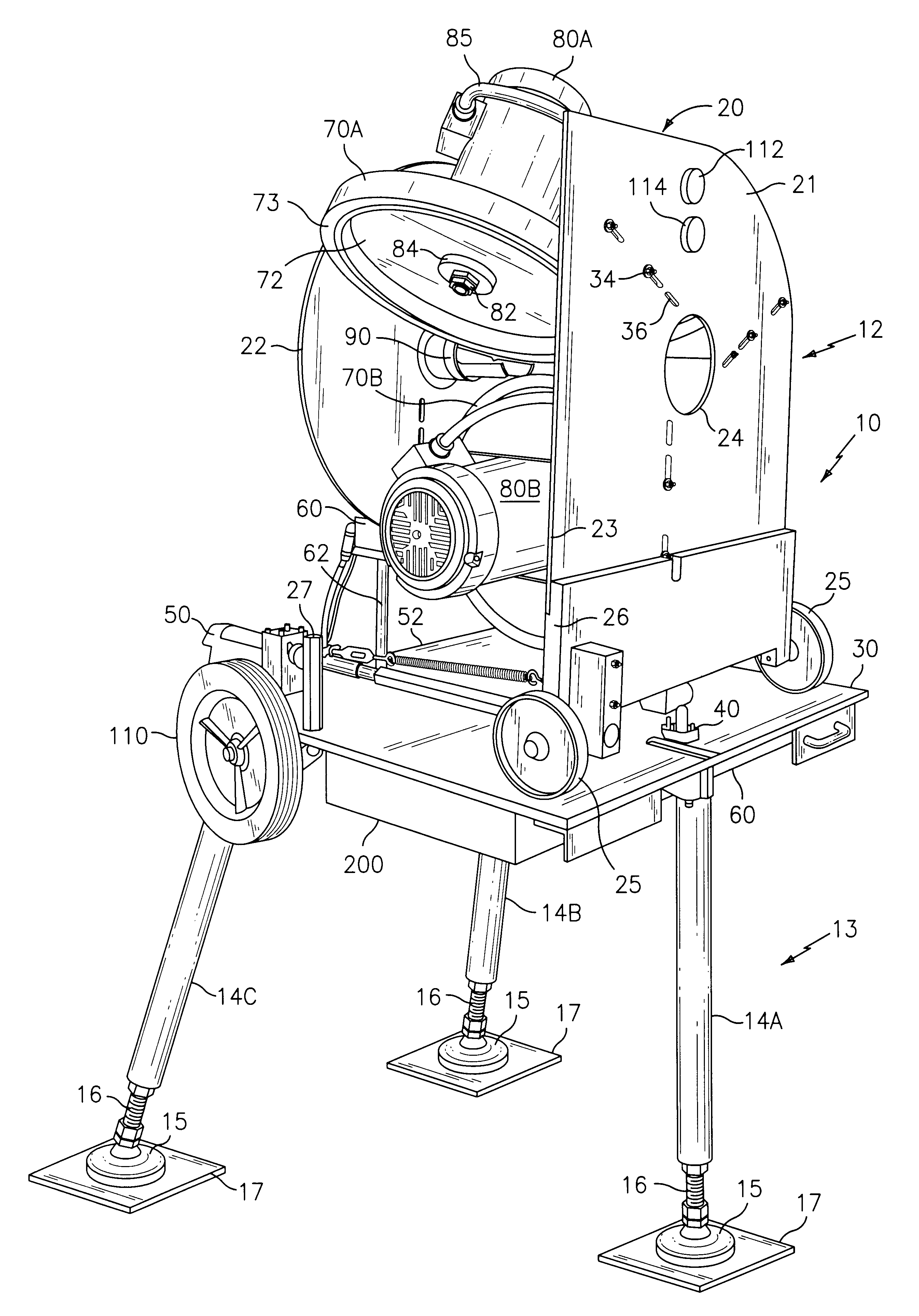
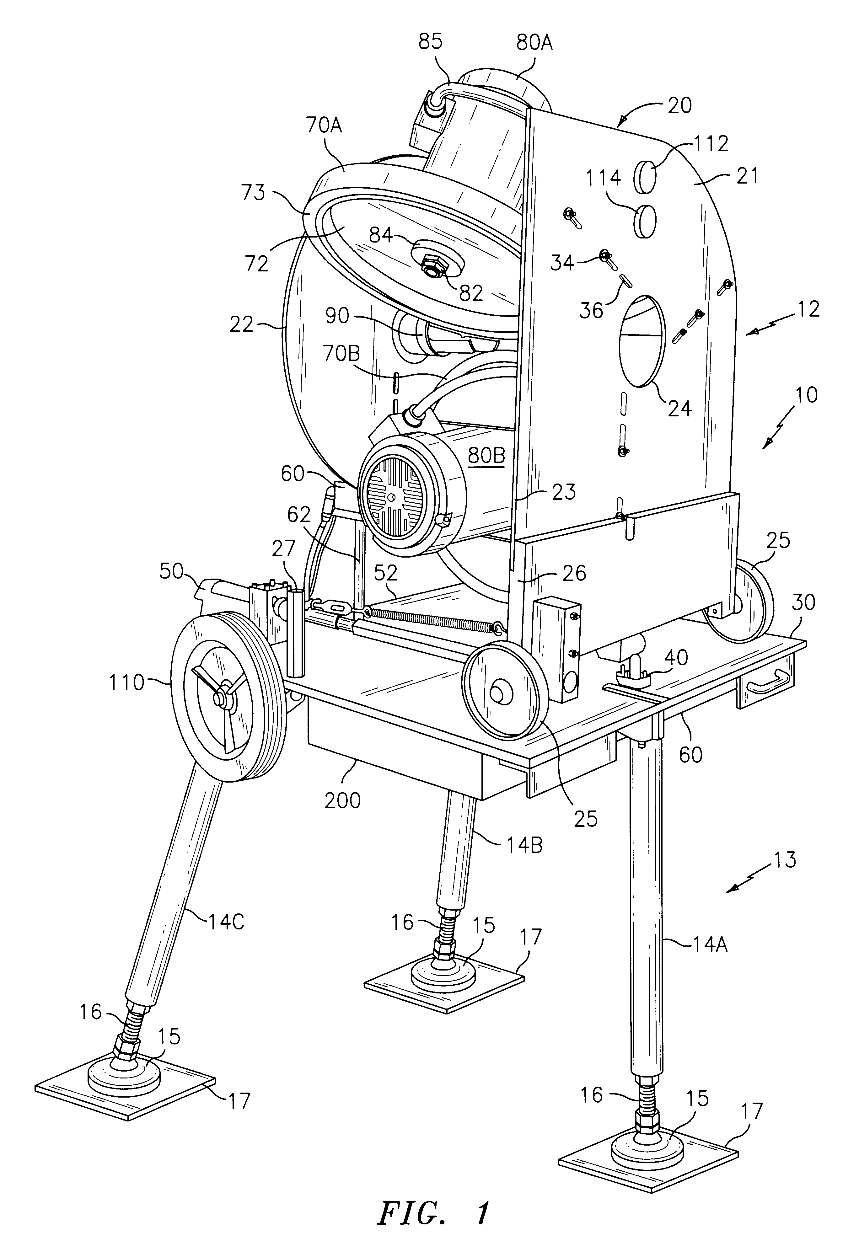
Referring to the drawings and, in particular, to FIG. 1 thereof, the ball-throwing machine of the present invention is provided and is referred to generally by reference numeral 10. The machine 10 includes an upper portion 12 that is mounted on a base 13 that includes a plurality of removable legs 14, preferably a front leg 14A and a pair of rear legs 14B and 14C, respectively, to form a tripod. A shock-absorbing device such as a shock absorber (not shown) may be included in the rear legs 14B and 14C to minimize the impact of any recoil of the machine 10 during use.

An enlarged foot 15 is provided at the outbound end of each leg 14 and is threadably secured to the leg 14 by threaded extension fitting 16 which permits the length of each leg 14 to be increased and decreased. A flat, rubberized plate 17 may be included at the bottom of each foot 15 to provide additional stability for the machine 10, particularly when used indoors such as, for example, on a gymnasium floor. Ball-throwing...


PUM


Abstract

A ball-throwing machine is provided which may be used for throwing baseballs, softballs and the like. The machine includes a power head having at least two and preferably three coacting wheels for propelling a ball toward a batter to simulate a pitch. Three AC motors and companion motor drives are provided for causing the wheels to rotate at predetermined speeds. The motor drives include dynamic braking circuits to permit rapid deceleration of the wheels. A pair of linear actuators is provided to permit the power head to be moved to predetermined horizontal and vertical positions. A programmable controller is included for individually controlling the rotational speed of each individual wheel, the horizontal position of the power head and the vertical position of the power head. A smart card reader may be employed for programming of the controller and the machine is adapted to be used in conjunction with a video display to simulate the actual pitching of a baseball by a pitcher. The machine is able to interchangeably deliver pitches of different types to different locations at different speeds with less than ten-second intervals between pitches.

Description

1. Field of the InventionThe present invention relates generally to a ball-throwing machine and, more particularly, to such a machine that is adapted to pitch baseballs and softballs and throw tennis and other balls interchangeably to different locations and at different speeds and with different spins. The invention has particular applicability as a baseball pitching machine that is able to interchangeably deliver a variety of pitches (i.e., fastballs, curveballs, changeups, etc.) at different speeds to different locations without the need for manually readjusting or repositioning the machine between pitches.2. Description of the Prior ArtPitching machines and ball-throwing machines are well-known in the art and generally fall into four categories: (1) machines that employ a spring actuated arm mechanism to propel the ball; (2) machines that employ at least one rotating wheel or a pair of rotating, coacting wheels to propel the ball; (3) machines that rely on pneumatic pressure to ...

Claims


Application Information

Patent Timeline
IPC IPC(8): A63B69/40G09B19/00A63B69/00A63B69/38
CPCA63B69/406G09B19/0038A63B69/38A63B2069/0008A63B2069/402A63B2225/15
Inventor BATTERSBY, GREGORY J.COBB, JAMESGRIMES, CHARLES W.SCHILE, RICHARD D.VAN GELDERN, STEVE
Owner PROBATTER SPORTS
Why Eureka
Try Eureka