
Combined router, ATM, WAN and/or LAN switch (CRAWLS) cut through and method of use

a router and switch technology, applied in data switching networks, frequency-division multiplexes, instruments, etc., can solve the problems of limited use synergy of routing and switching technologies, limited functional combination of routers and switches, and inability to use routing and switching technologies. to achieve the effect of improving data throughpu

Inactive Publication Date: 2001-02-06
IBM CORP
View PDF5 Cites 61 Cited by
  • Summary
  • Abstract
  • Description
  • Claims
  • Application Information

AI Technical Summary

Benefits of technology

It is yet another object of the present invention to provide a method of cut-through in combined routing and switching devices used in local area and wide area computer networks to improve data throughput.

Problems solved by technology

LANs are generally limited to computers within a relatively small area, such as a building, office or campus.
However, although physically combined in a single package for use at network nodes, functional combination of routers and switches has been limited.
Generally routers in such combined packages communicate with the network through the switches, but routing and switching technologies are not being used synergistically in networks to take full advantage of both technologies.

Method used


Image

  • Combined router, ATM, WAN and/or LAN switch (CRAWLS) cut through and method of use
  • Combined router, ATM, WAN and/or LAN switch (CRAWLS) cut through and method of use
  • Combined router, ATM, WAN and/or LAN switch (CRAWLS) cut through and method of use

Examples


Embodiment Construction

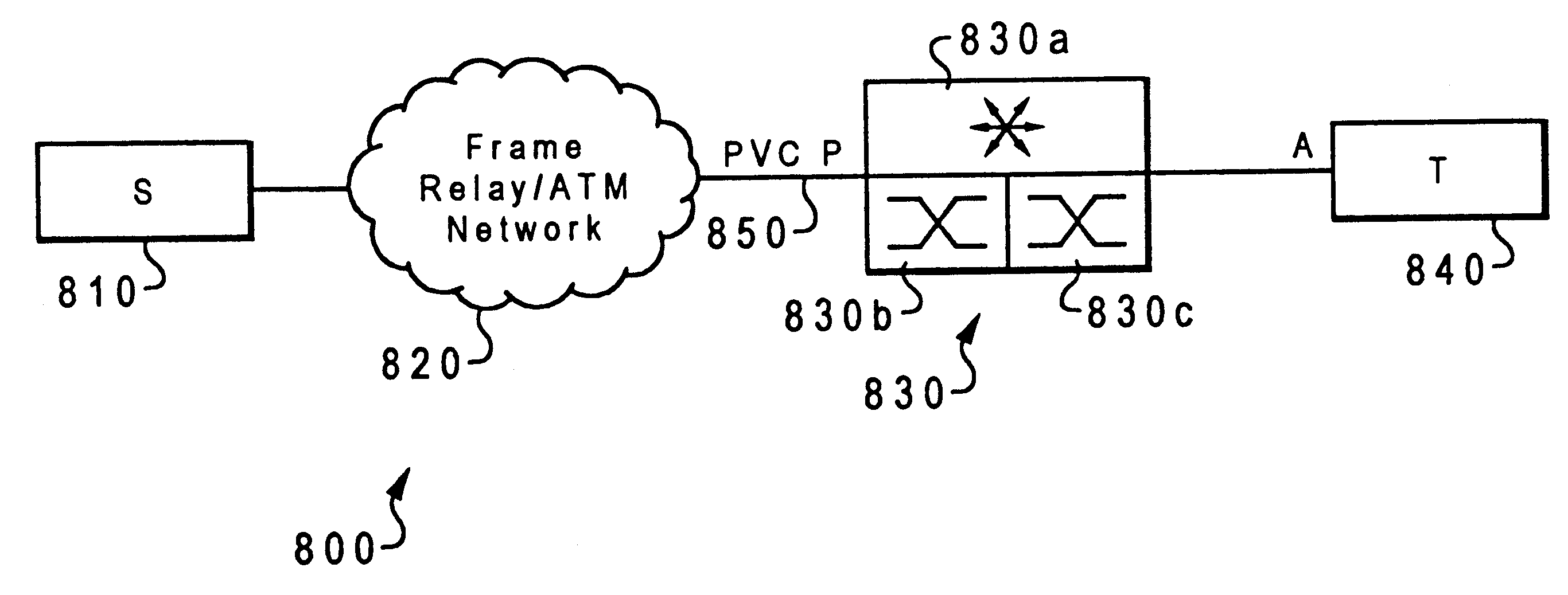
With reference now to the figures and in particular with reference to FIG. 8, a simple example of combining router and switch technologies for use in a preferred embodiment of the present invention is illustrated. The combination router / switch 100 includes an IP router 110 connected with an ATM switch 120 through an internal connection 130. Frame traffic from a source 140 or 142 to be routed by router 110 is received by switch 120. Internal connection 130, which has a ATM-type address, allows switch 120 to forward this frame traffic to router 110. Frames forwarded from router 110 to another network node 150 or 152 are passed through switch 120.

Referring to FIG. 9, a more sophisticated but more generally useful example of synergistically combining routing and switching technologies for use in a preferred embodiment of the present invention is depicted. The combined router / switch 200 includes a router 210 which may handle multiple routing protocols such as IP 211, IPX 212, and HPR 213...


PUM


Abstract

A cut through is provided in a combined router / switch in a data processing system network by having the router store and forward a first portion of a data flow from a source to a destination. The router determines whether the data flow is suitable for cut through. If found suitable, the router sends a redirect protocol to the source, directing the source to use a different destination address for all or part of the remainder of the data flow. The portion of the data flow having new destination address is then cut through the combined router / switch by the switch. If the cut through has a failure, responsibility for the data flow delivery returns to the router. If the destination of a cut through data flow is unavailable, the frames are stored by the switch and forwarded when the destination is available.

Description

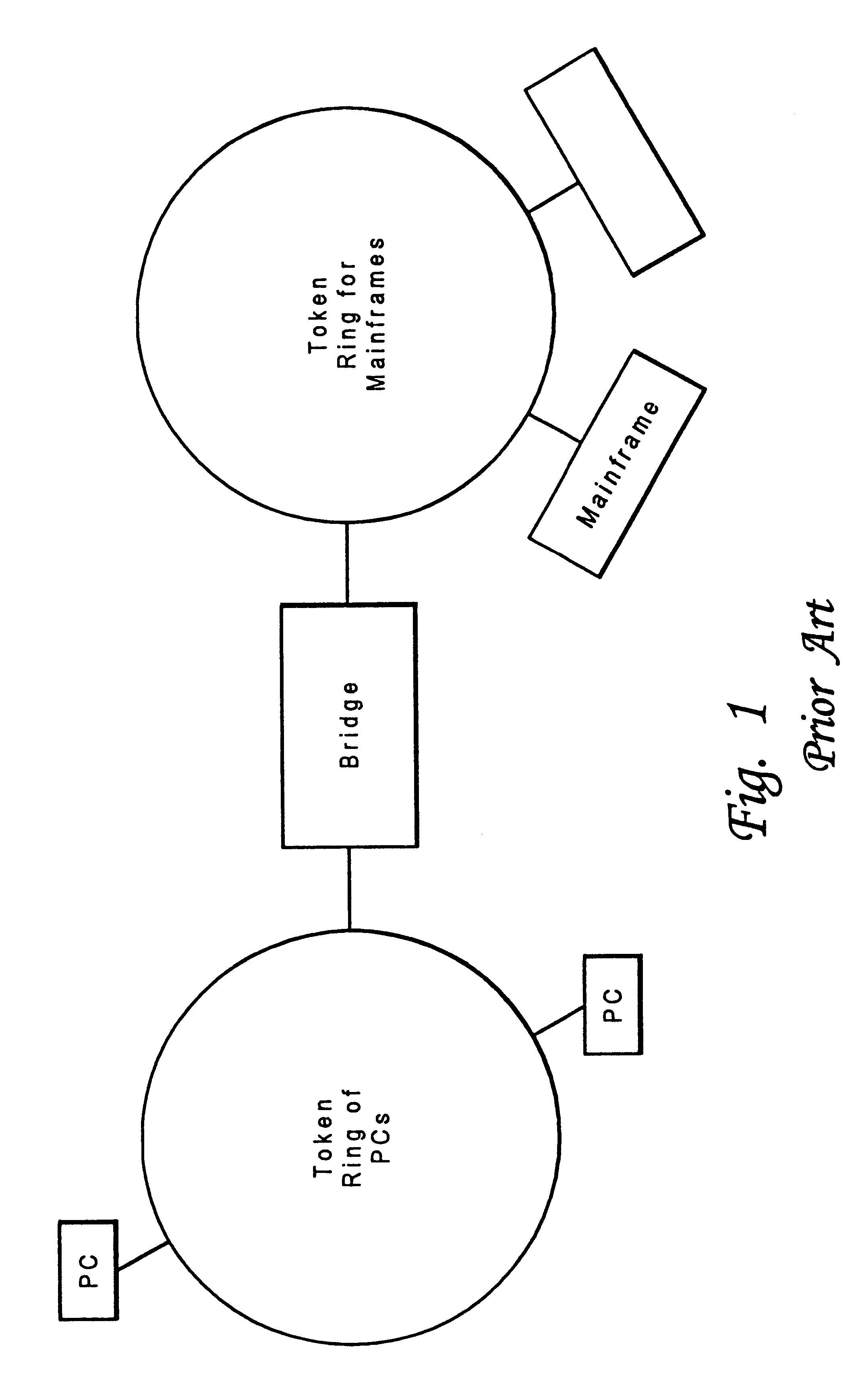
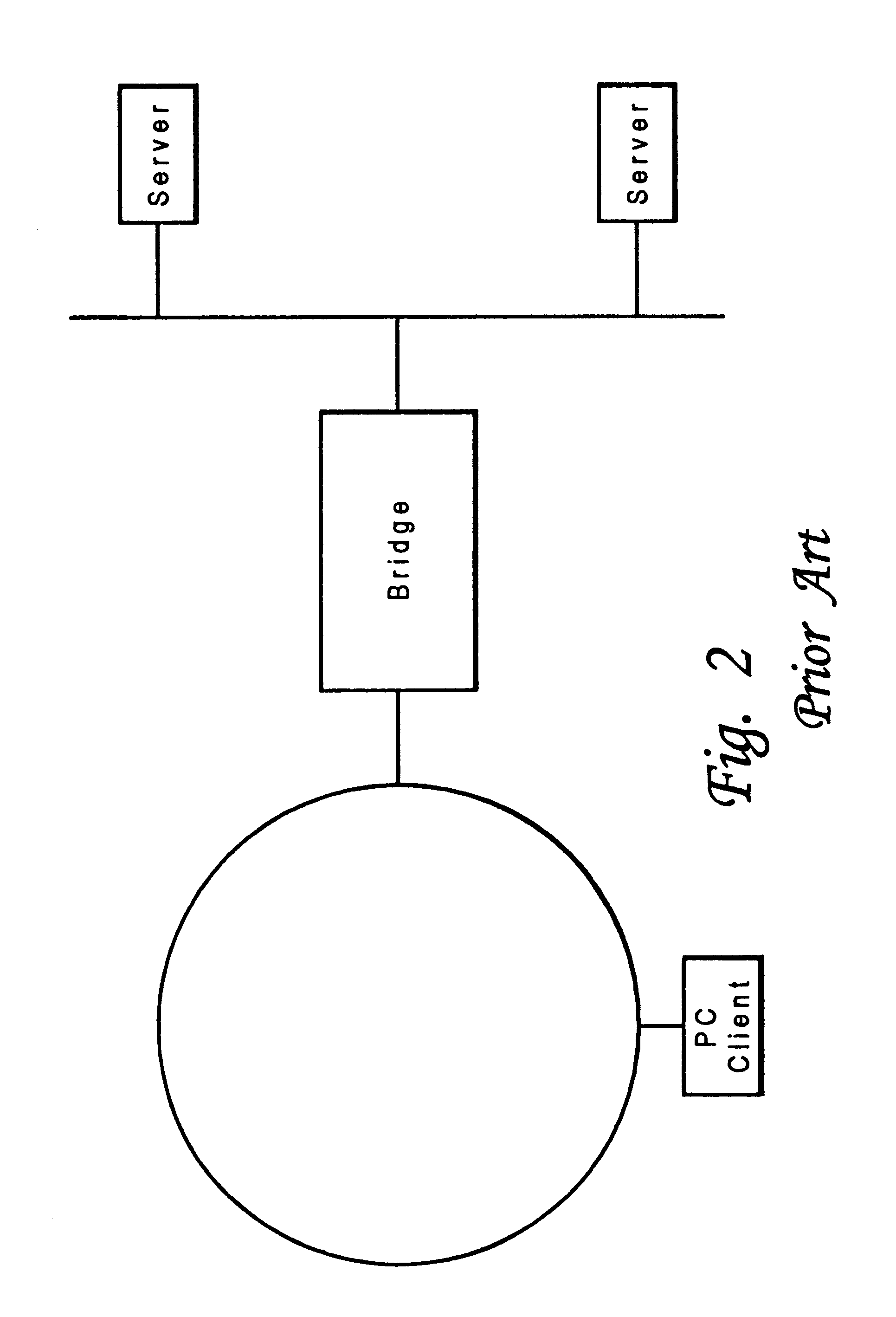
BACKGROUND OF THE INVENTION1. Technical FieldThe present invention relates in general to combined routing and switching devices in computer networks and in particular to such devices in local area network and wide area network environments. Still more particularly, the present invention relates to improving performance of combined routing and switching devices used in local area networks and wide area networks by providing a cut-through.2. Description of the Related ArtThe past decade has seen an explosion in the use of computer networks in all sectors of society: business and industry, education and research, and even recreation. This growth in the use of computer networks has been accompanied by a proportional demand for improvement of the performance of such networks.Computer networks are classified by their geographic scope. The most commonly used terms for classifying computer networks are local area network (LAN) and wide area network (WAN). LANs are generally limited to compu...

Claims


Application Information

Patent Timeline
IPC IPC(8): H04Q11/04H04L12/56
CPCH04L12/5601H04L49/602H04Q11/0478H04L49/251H04L49/351
Inventor AHO, MICHAEL E.
Owner IBM CORP
Learn More