Acoustic logging apparatus and method

a technology of acoustic logging and acoustic well, which is applied in the direction of seismology for water logging, using reradiation, instruments, etc., can solve the problems of the method described above for determining the orientation and velocity of slow and fast shear wave, and the undesired cost of the acoustic logging tool

Inactive Publication Date: 2001-02-13
HALLIBURTON ENERGY SERVICES INC
View PDF22 Cites 55 Cited by
  • Summary
  • Abstract
  • Description
  • Claims
  • Application Information

AI Technical Summary

Problems solved by technology

The methods described above for determining slow and fast shear wave orientations and velocities require extensive computation and may suffer because the solution for .theta. is ambiguous (i.e. is satisfied both by .t

Method used


Image

  • Acoustic logging apparatus and method
  • Acoustic logging apparatus and method
  • Acoustic logging apparatus and method

Examples


Embodiment Construction

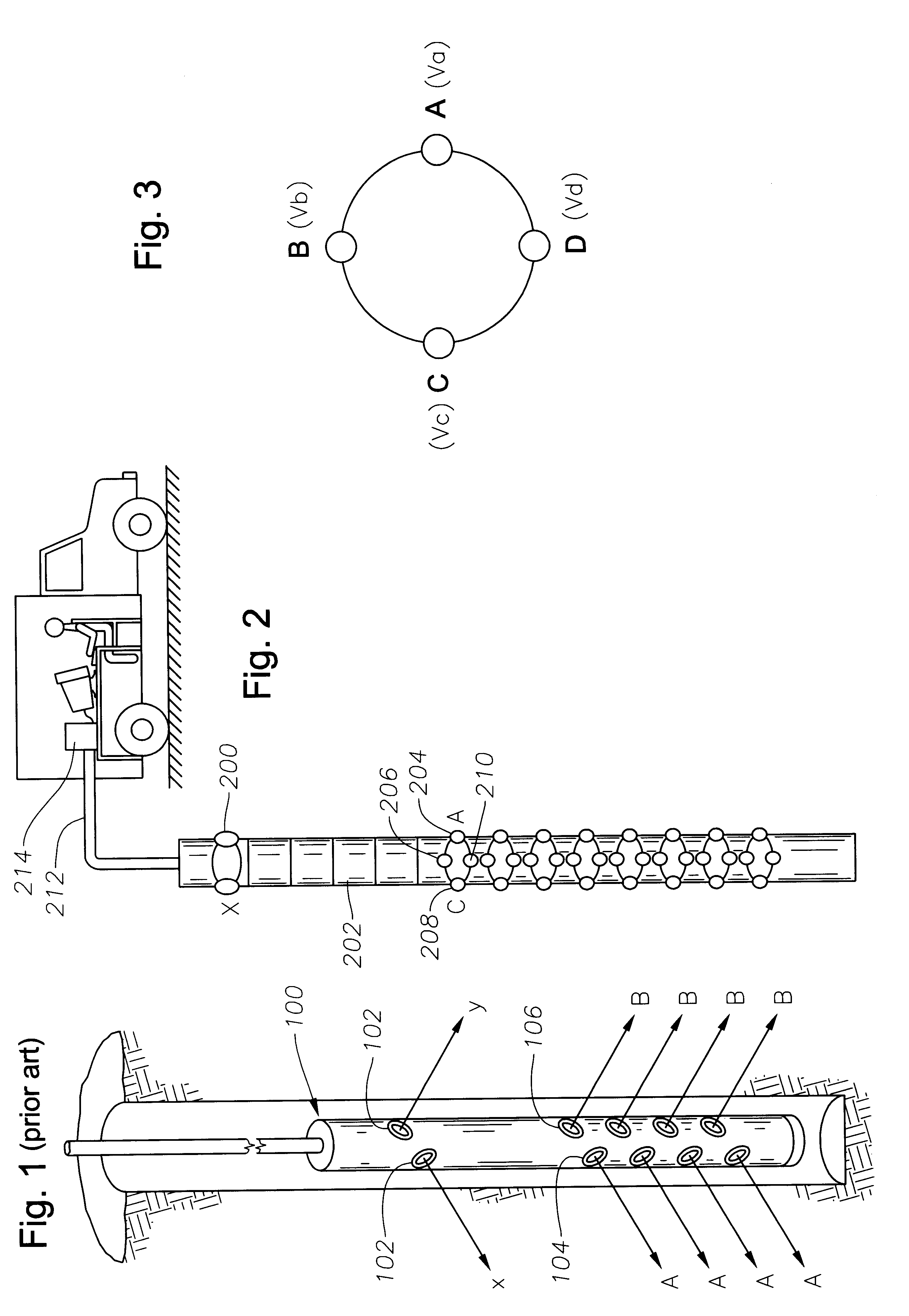
A preferred embodiment of the acoustic logging tool is shown in FIG. 2. A single dipole source 200 emits sound into the formation which propagates as a wave along the borehole. An isolator 202 prevents unwanted signal components from travelling down the acoustic logging tool shaft. Receivers A, 204, B, 206, C, 208 and D, 210 with angular separation of 90.degree. from adjacent receiver receive acoustic signals from source 200 as these signals travel along the borehole. Additional levels of receivers may also be provided on the tool. The four receivers at each level record the waveforms from the source. The four receivers may be at any arbitrary radial distance from the tool axis. After conversion to a digital format, the receiver waveform data is compressed and sent through a wire line 212 to a computer 214 uphole. If the tool is used for logging while drilling (LWD), the compressed waveform data is stored on a memory device inside the tool. In FIG. 2, the preferred embodiment of the...


PUM


Abstract

An apparatus and method for determining fast and slow shear wave velocities and orientations in an anisotropic earth formation that reduces the error and ambiguity in calculating these parameters and eliminates the need for dipole receivers and multiple dipole sources. The apparatus generally includes a single dipole source capable of generating an acoustic signal within a borehole. The acoustic logging tool contains multiple levels of receivers. At each level, four receivers, which may be conventional pressure transducers, receive shear/flexural wave signals which propagate along the borehole earth formation. These receivers measure the pressure fields from the wave signals. A processing device, preferably a UNIX(TM) based computer, interpolates the measured pressure fields between any two adjacent receivers. The processing device performs cross-component decomposition on the pressure field to determine shear wave orientation and velocity. Using the shear wave orientation and velocity the processing device determines transit time anisotropy, energy anisotropy, and slowness anisotropy.

Description

1. Field of the InventionThe present invention generally relates to acoustic well logging. More particularly, the present invention relates to a new system and method for determining slow and fast shear wave velocities and orientations in an earth formation using receiver signals from an acoustic well logging instrument to determine shear wave anisotropy from a single dipole source.2. Description of the Related ArtIt is well known that mechanical disturbances can be used to cause acoustic (sound) waves in earth formations and that the properties of these waves, also called seismic waves, can be measured to obtain important information about the formations through which the waves have propagated. In particular, parameters of acoustic waves, such as their velocity and direction of particle motion (polarization direction) can be indicators of formation characteristics that help in evaluation of the location and / or producibility of hydrocarbon resources. Methods for determining shear wa...

Claims


Application Information

Patent Timeline
IPC IPC(8): G01V1/50G01V1/40
CPCG01V1/50
Inventor MANDAL, BATAKRISHNA
Owner HALLIBURTON ENERGY SERVICES INC
Why Eureka
Try Eureka