
Dynamic fiber optic switch with artificial muscle

a fiber optic switch and dynamic technology, applied in the field of fiber optic switches, can solve the problems of complicated configuration of patents or the need for additional mechanical means beyond these materials

Inactive Publication Date: 2001-02-20
STC UNM +2
View PDF20 Cites 19 Cited by
  • Summary
  • Abstract
  • Description
  • Claims
  • Application Information

AI Technical Summary

Benefits of technology

A primary advantage of the present invention is that it does not require additional mechanical means beyond the electro- or magneto-active materials adhered directly to the fiber.
Still another advantage of the present invention is that the optical fiber can be moved in 2-1 / 2 dimensions.
Other potential advantages provided by the present invention, due to its simplicity and design, are long life, reliability, low cost, and a variety of applications.

Problems solved by technology

The Ohashi, Ramsey, Ninnis, Stanley, Jebens, Glass, and Laor patents disclose various methods and apparatuses that use piezoelectrics, magneto-strictive materials, and shape memory alloys, for bending the fiber; however, these patents are either complicated in their configurations or require additional mechanical means beyond these materials.

Method used


Image

  • Dynamic fiber optic switch with artificial muscle
  • Dynamic fiber optic switch with artificial muscle
  • Dynamic fiber optic switch with artificial muscle

Examples


first embodiment

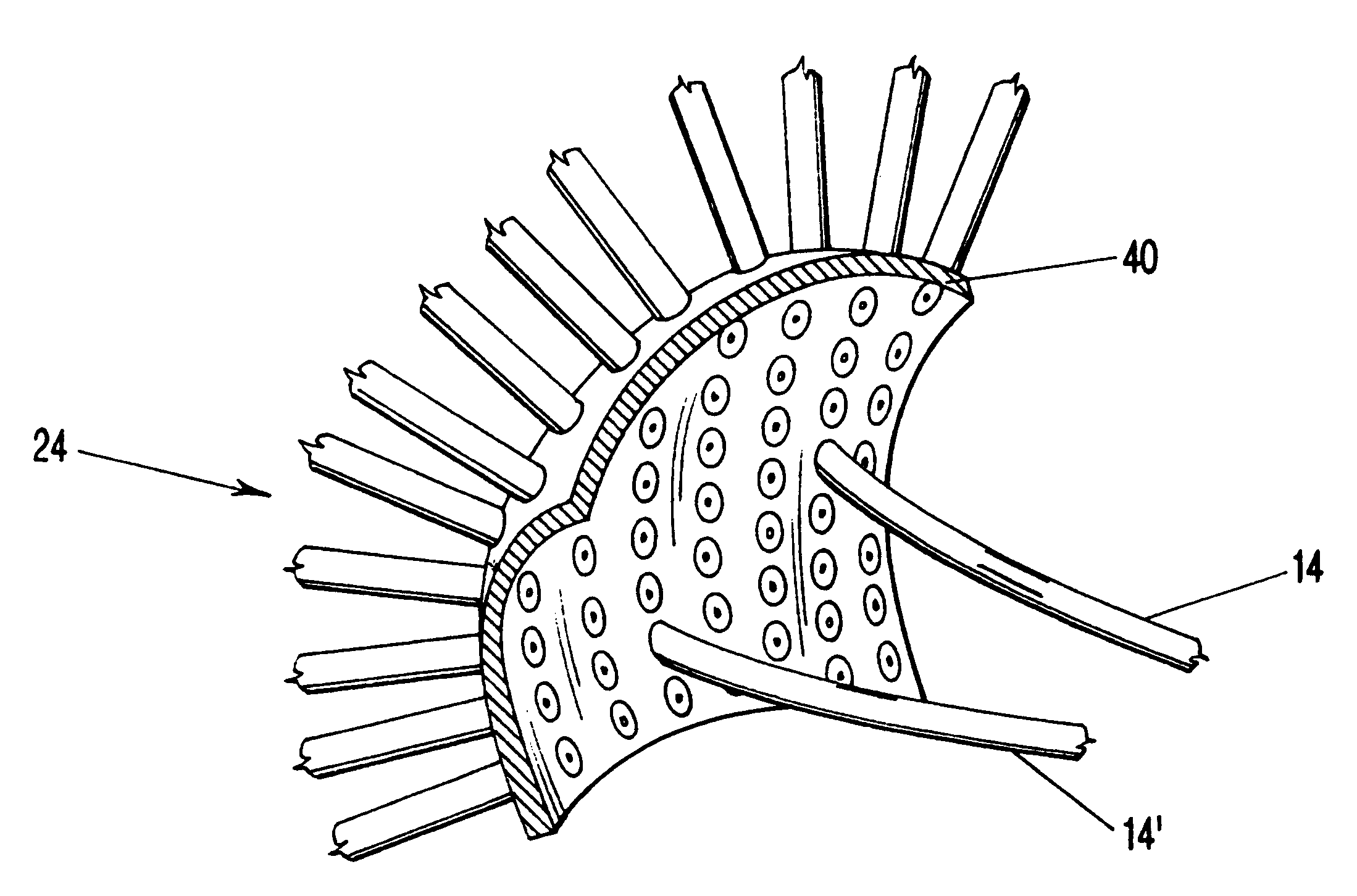
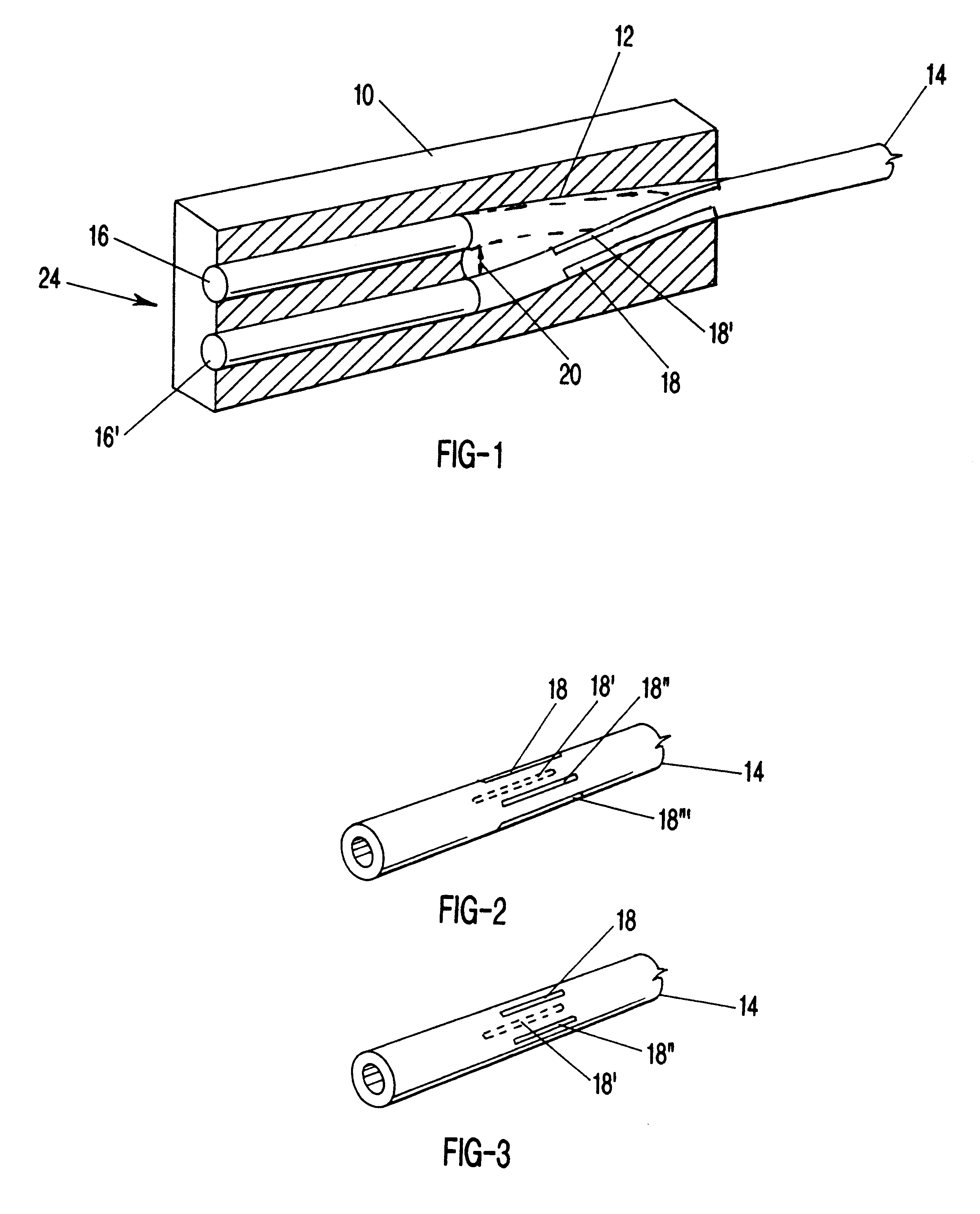
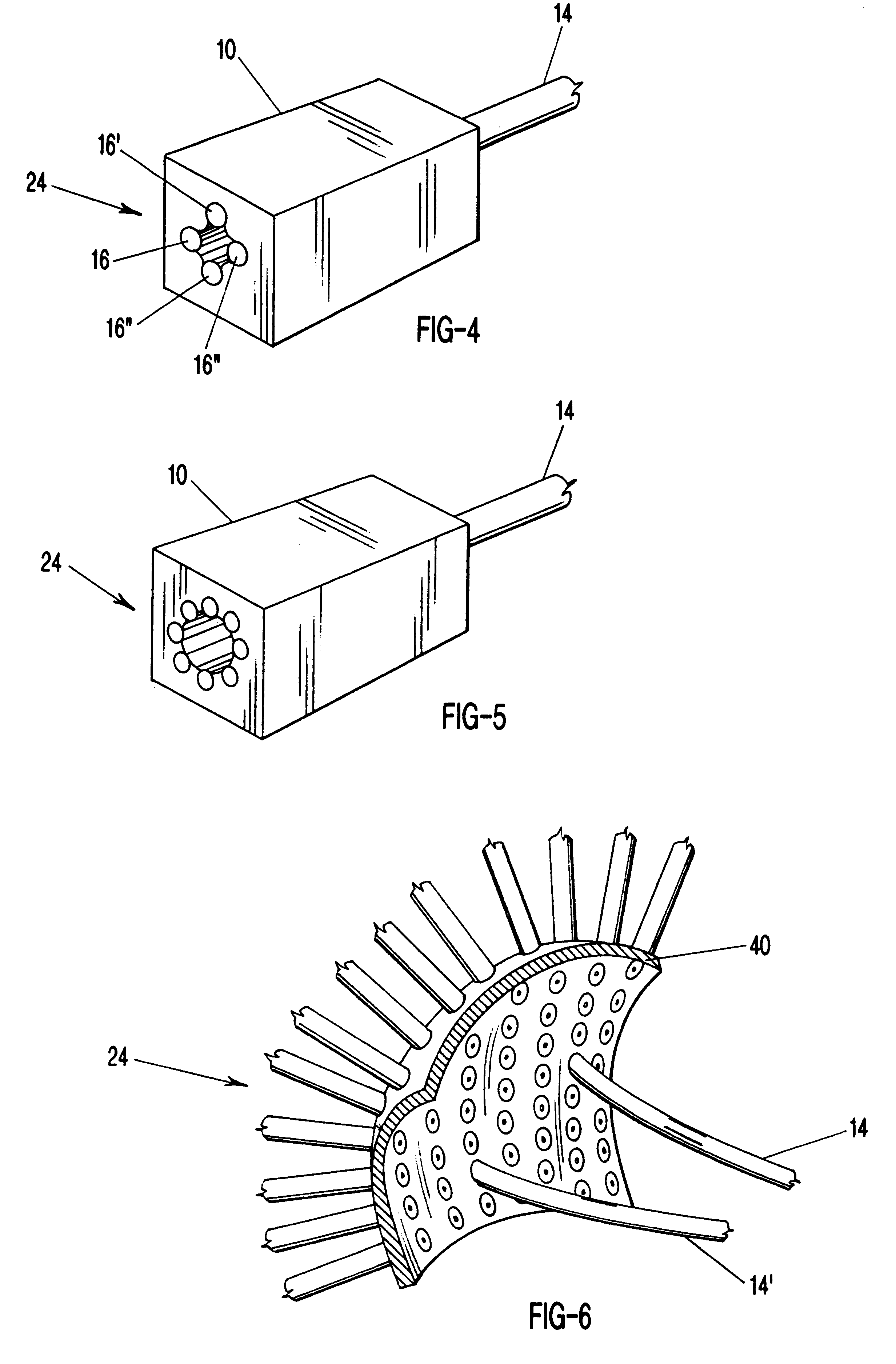
In a first embodiment, a plurality of magneto-strictive strips, such as Terfenol-D, approximately a few centimeters long, for example two cm, and of a width of a few microns are adhered in a symmetrical fashion longitudinally to each fiber near the end to be undulated. These activation strips are powered by an imposed magnetic field and either expand or contract according to the polarity of the magnetic field. The magnetic field is normally produced around a magneto-strictive material by a coil arrangement. In this embodiment, the coil is attached to or embedded in the activation strip and the coil is powered by a voltage supply connected to each activation strip in the same way as described below for other embodiments. By controlling the magnetic field applied to each individual activation strip, the end of the optical fiber undulates dynamically and quickly to perform the switching function. For example, if two magneto-strictive strips are placed 180 degrees opposite each other lo...

fourth embodiment

In a fourth embodiment, a plurality of ionic polymeric metal composite, IPMC artificial muscle, activation strips approximately a few centimeters long, such as two cm, and of a width of a few microns are adhered in a symmetrical fashion longitudinally to each fiber near the end to be undulated. Artificial muscles in the form of strips with electrodes sputtered or plated on their surfaces across their thickness, naturally bend when subjected to a low voltage of a few volts, such as 2-5 volts, and amperages of approximately a few hundred milliamps. By "natural bending," one side contracts and one side expands, in distinction to magneto-strictive, piezoelectric, piezoceramic, piezo-polymeric or shape-memory materials, which expand or contract more or less uniformly. The underlying theory is that ions within the material migrate to one side or the other and in doing so carry water with them causing swelling on one side (expansion) and deswelling on the other side (contraction). The stri...

fifth embodiment

In a fifth embodiment, an appropriately electroded sleeve or tubular jacket of ionic polymeric conductor composite, IPMC artificial muscle, approximately a few centimeters long, such as two cm, and of a thickness of a few microns is adhered on the cylindrical mantle of each fiber near the end to be undulated. FIGS. 10a and 10b show a side view and a cross-sectional view, respectively, of the IPMC artificial muscle wrapped around optical fiber 14 as a jacket 50. Voltage supply 30 operated by switch 32 provides voltage to electrodes 34 and 36 upon IPMC jacket 50. Upon closing switch 32, voltage is supplied to electrodes 34 and 36, causing jacket 50 as a whole to bend in an upward direction. Additional electrode pairs are attached elsewhere upon jacket 50 to cause jacket 50 to bend in other directions as well.


PUM


Abstract

An optical switch comprised of an artificial muscle activation material that is adhered longitudinally around an optical channel, such as an optical fiber or group of fibers, to cause the channel to undulate in 2-½ dimensions when the material is activated by a voltage source via electrodes on the surface of the artificial muscle activation material. The material can be applied to the optical channel in a series of longitudinal strips or as a jacket surrounding the channel. When activated by a voltage source, be it a constant source or a variable source varying in amplitude, frequency or polarity, the artificial muscle material bends, causing the optical channel to also bend. The artificial muscle activation material can be formed into an optical channel itself when formed into a channel and cladded to have internal reflection.

Description

A related application entitled "Dynamic Fiber Optic Switch" is being concurrently herewith, to Albert Goodman, Attorney Docket No. 70350-9101, and the specification thereof is incorporated herein by reference.1. Field of the Invention (Technical Field)The present invention relates to fiber optic switches, particularly the use of electro- or magneto-active materials to cause optical fibers to undulate.2. Background ArtNote that the following discussion refers to a publication by author(s) and year of publication, and that due to recent publication dates certain publications are not to be considered as prior art vis-a-vis the present invention. Discussion of such publication herein is given for more complete background and is not to be construed as an admission that the publication is prior art for patentability determination purposes.Present day optical fiber technologies are revolutionizing the telecommunications industry. Tremendous advances have been made in the field of telecommu...

Claims


Application Information

Patent Timeline
IPC IPC(8): G02B6/35
CPCG02B6/3502G02B6/3558G02B6/3572G02B6/3578
Inventor GOODMAN, ALBERTSHAHINPOOR, MOHSEN
Owner STC UNM
Learn More