Airflow control valve for a clean room

a technology for controlling valves and clean rooms, which is applied in the direction of multiple way valves, process and machine control, domestic heating, etc., can solve the problems of affecting the flow rate through the other dampers in the system, prone to inaccurate settings, and time-consuming balancing methods, so as to reduce the risk of affecting the flow rate of the entire hvac system, the supply or exhaust pressure is still subject to changes, and the demand requirements are changed

Inactive Publication Date: 2001-02-27
SYNETICS SOLUTIONS +2
View PDF20 Cites 80 Cited by
  • Summary
  • Abstract
  • Description
  • Claims
  • Application Information

AI Technical Summary

Problems solved by technology

Furthermore, when the amount of dampening is changed in a particular damper, the pressure throughout the entire HVAC system will change, thereby affecting the flow rate through the other dampers in the system.
One problem with maintaining accurate airflow in systems is in balancing the airflow through different regions.
Such a balancing method is time consuming, tedious, prone to inaccurate settings, and not responsive to external changes in the airflow supply system.
Furthermore, after the balancing is completed, the entire HVAC system is still subject to changes in supply or exhaust pressure and to changes in the demand requirements of various components of the HVAC system, any of which could require having to rebalance the system.
Another problem that arises in large manufacturing applications that have multiple minienvironments and complex HVAC systems, is balancing the overall system and providing feedback and information regarding the current state of operations to the equipment and facility operators.
Due to many factors, a balanced process tool can eventually become "unbalanced" and corrupt the manufacturing process inside the minienvironment.
Furthermore, it is typically not known how changes in damper or fan speed settings of a particular subsystem or minienvironment will affect the HVAC system in general, or particular subsystems.
Such effects can only be determined by making individual measurements at discrete locations within the HVAC system, and making changes as necessary, which changes may cause still further effects at other locations within the HVAC system.
Another problem with some manufacturing applications is the presence of chemicals or fumes that are acidic or alkaline that can react with, or otherwise adversely affect, dampers or controls in the HVAC system.
Such chemicals or fumes can, for example, corrode dampers or controls that are in contact with the chemicals in the airflow, causing them to operate incorrectly.
In addition, the escape from the system of noxious gases can cause a safety problem for workers using or maintaining the equipment.
Another problem with some manufacturing applications is retrofitting existing systems to provide automated measurement and control systems.
Therefore, if there are only two plates, this position results in an essentially blocked airflow.

Method used


Image

  • Airflow control valve for a clean room
  • Airflow control valve for a clean room
  • Airflow control valve for a clean room

Examples


Embodiment Construction

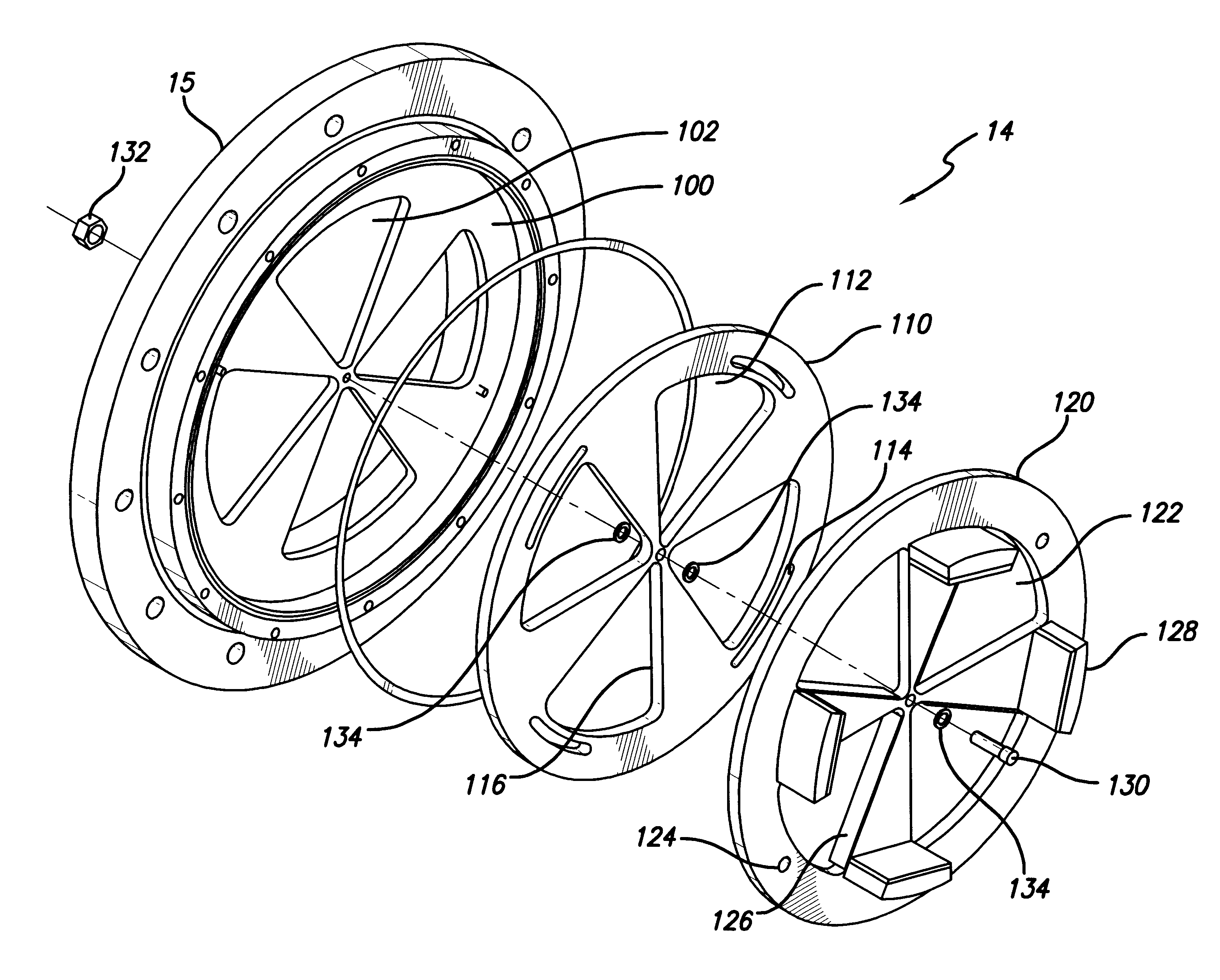
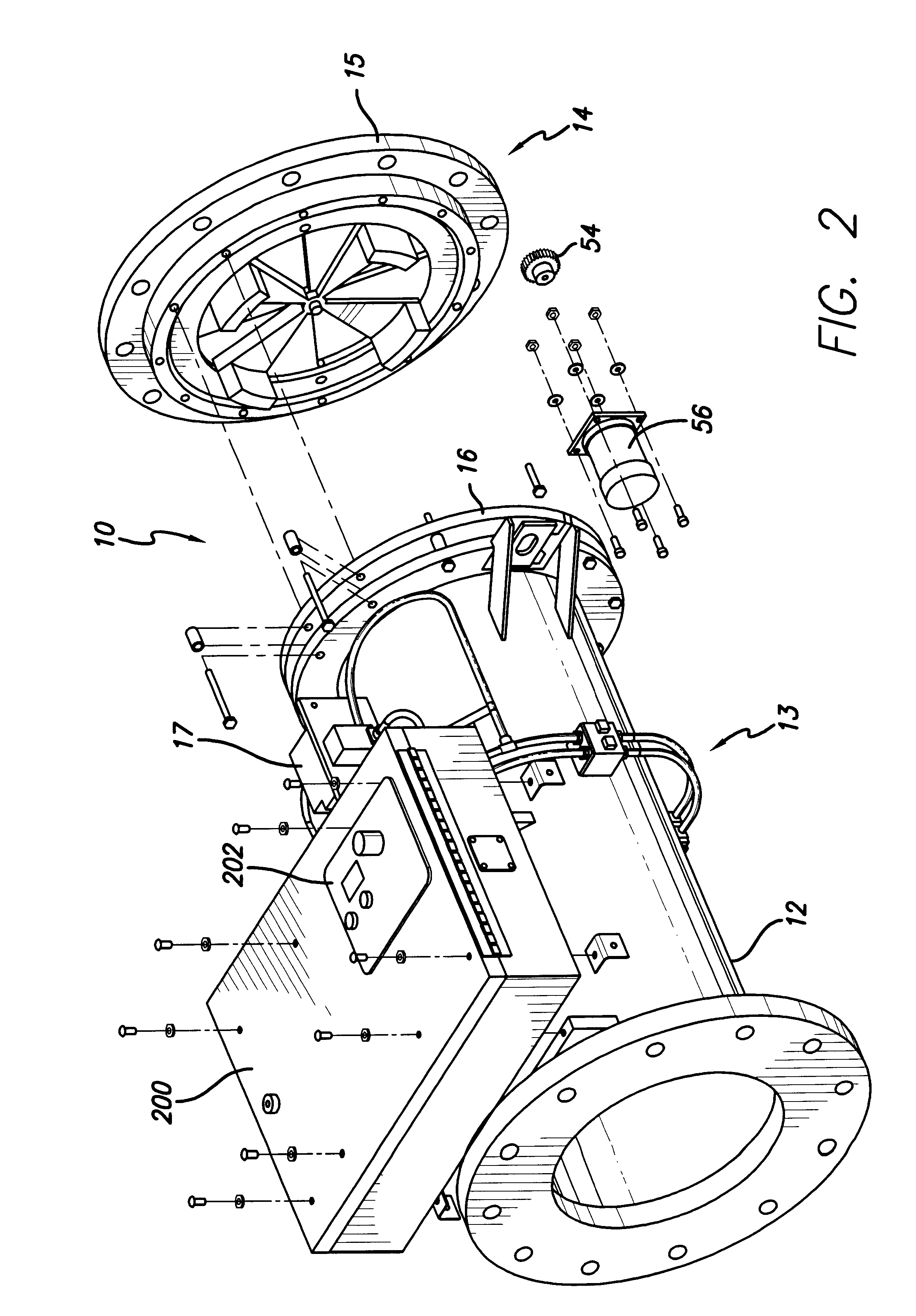
, one way in which the plates could be moved is through use of a stepper motor that drives a rotatable shaft, and in turn a gear, a predetermined incremental rotational amount each time it receives a signal from the damper control system. The gear in turn is coupled, either magnetically or mechanically, to at least one of the plates, such that when the gear is rotated, it effects a corresponding rotation in the plates.

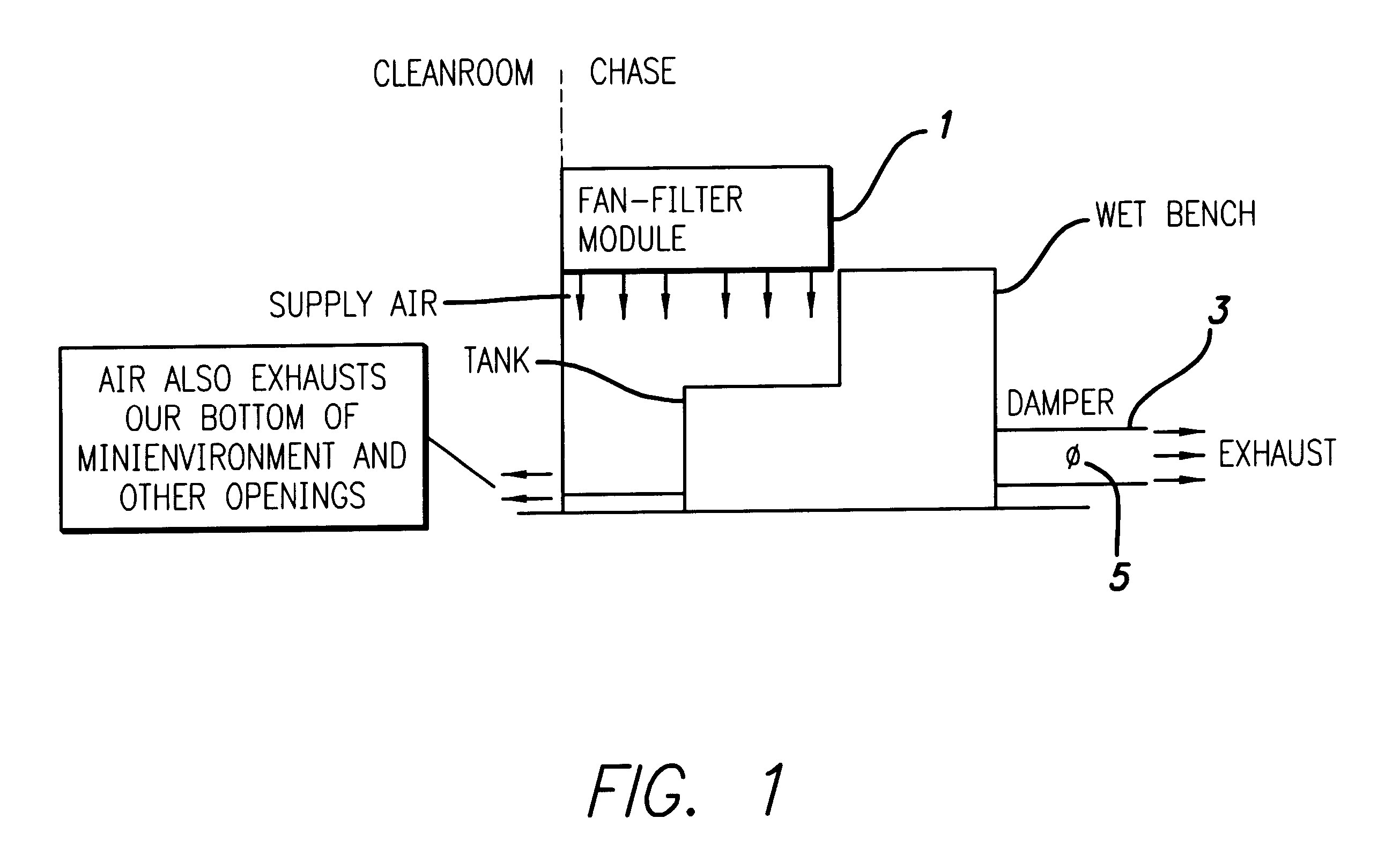
Another aspect of the present invention is an optional alarm to indicate when an airflow exists that is below the desired range and cannot be brought into an acceptable range through adjustment of the damper. Such a condition might occur, for example, if the HVAC system airflow supply or exhaust system is interrupted or blocked. In such a situation, no adjustment of the damper would be possible to adjust the airflow rate into the acceptable range. In that case, the control system can be programmed to sound an alarm or produce an alarm signal to indicate that there is l...


PUM


Abstract

An airflow control valve for a clean room having a duct section with a damper positioned within the duct. The damper being capable of an adjustment from an open position to a closed position. The opening and closing of the duct is accomplished through a magnetic coupling such that the duct can remain sealed during operation. The airflow control valve includes a sensor for measuring the airflow rate, so that the duct can be adjusted to maintain one or more predetermined flow rate set-points.

Description

The invention described in this document generally relates to controlling the airflow into clean rooms and small clean room enclosures ("minienvironments") of the sort used in silicon wafer manufacturing. More specifically, the invention relates to airflow control valves or dampers for controlling, maintaining and monitoring the flow of air through manufacturing environments such as clean rooms and minienvironments that require precise control of airflow and exhaust.BACKGROUND INFORMATIONMany manufacturing applications rely on a heating, ventilating, and air conditioning ("HVAC") system to control environmental conditions such as temperature and humidity, or to provide ventilation or exhaust of hazardous fumes. In such systems, the air flow is typically controlled using dampers located at various points within ducts in the HVAC system. These dampers may be, for example, gate valves, butterfly valves, or blast valves, and may be fixed, adjustable or motorized. By increasing or decrea...

Claims


Application Information

Patent Timeline
Patent Type & Authority Patents(United States)
IPC IPC(8): F16K3/02F16K3/08F24F3/16G05D7/06F24F13/14
CPCF16K3/085F24F3/161G05D7/0635F24F2011/0038F24F2013/148F24F2110/30Y10T137/8704Y10T137/86743Y10T137/7759Y10T137/87032F24F3/167
Inventor MACGIBBON, BRUCE S.WOLOCHUK, MARK C.WOLOCHUK, LEE I.SIROVY, CHRISTOPHER P.LEBARON, JAMES F.YARROLL, JEFFREY W.
Owner SYNETICS SOLUTIONS
Why Eureka
Try Eureka