Rear suspension system for bicycle

a rear suspension and bicycle technology, applied in the field of rear suspension systems for bicycles, can solve the problems of sprung mass to bob up or down, inability to extend further, and total inactivity

Inactive Publication Date: 2001-03-13
GUENTHER PETER
View PDF12 Cites 52 Cited by
  • Summary
  • Abstract
  • Description
  • Claims
  • Application Information

AI Technical Summary

Benefits of technology

Preferably, during suspension action, the rear axle follows an approximate arc centred on the bottom bracket. Mos...

Problems solved by technology

A problem that all rear suspension designers have to address is the elimination of undesirable effects associated with rear suspension including those which have been loosely referred to by cyclists as "bio-pacing".
Regardless of whether the suspension is compressed or extended by pedaling forces, this is wasted energy which causes the sprung mass to bob up or down with each pedal stroke.
A very positive N-factor may result in the suspension "locking out" or "topping out" in which case the suspension may be totally inact...

Method used


Image

  • Rear suspension system for bicycle
  • Rear suspension system for bicycle
  • Rear suspension system for bicycle

Examples


Embodiment Construction

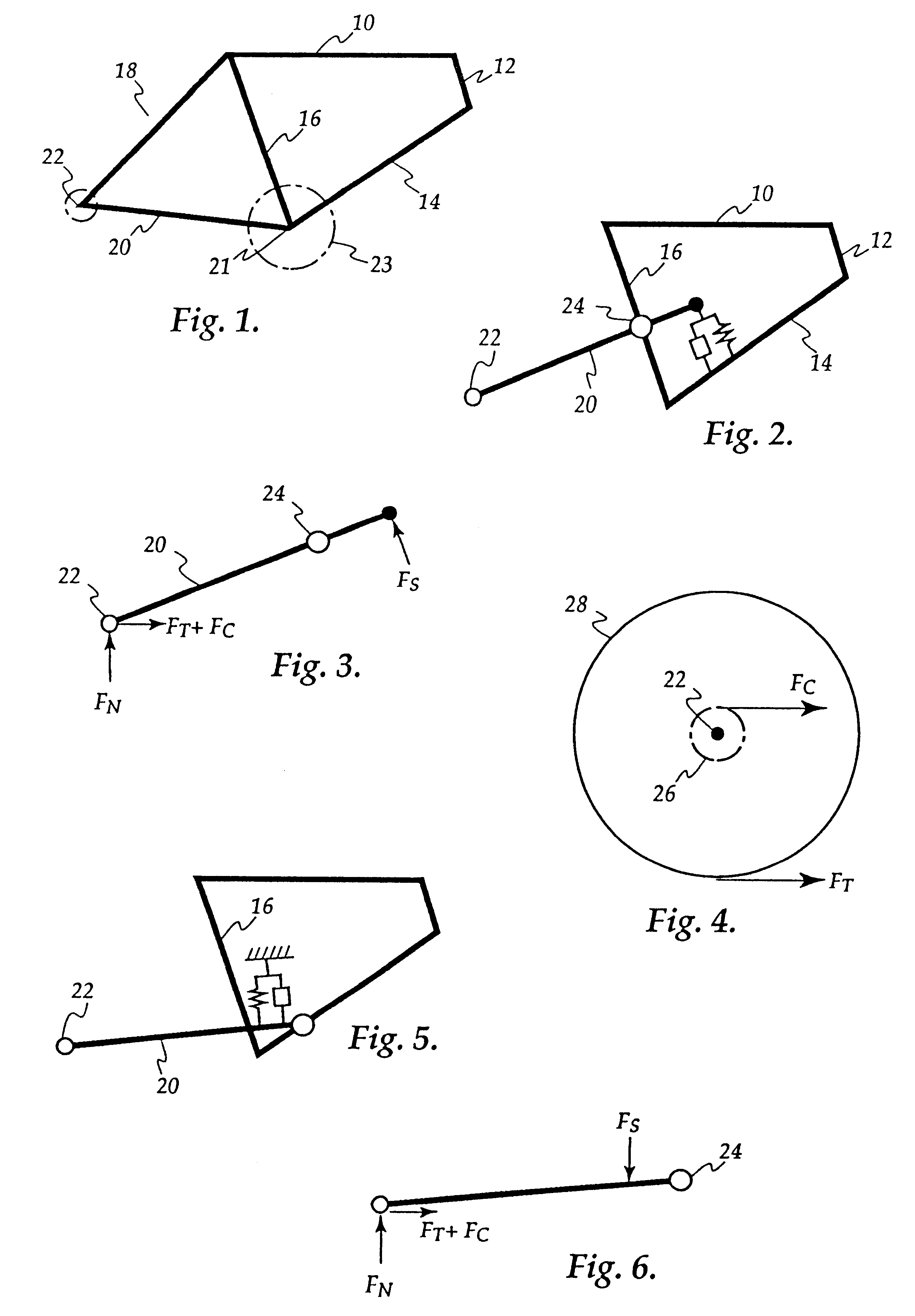
Referring firstly to FIG. 1, there is illustrated a conventional frame for the purpose of establishing nomenclature.

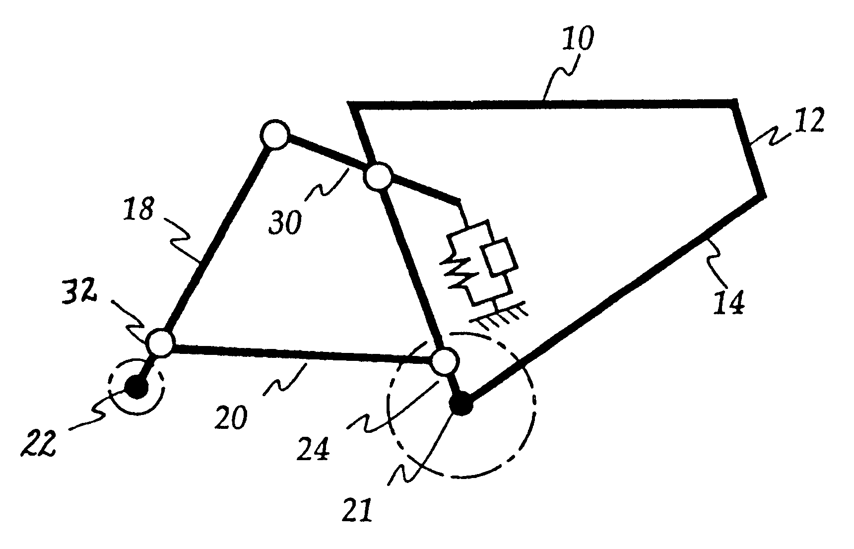
A conventional frame consists of a top tube 10, head tube 12, down tube 14, seat tube 16, seat stays 18 and chain stays 20.

The rearward ends of the chain stays include drop outs for accomodating the rear wheel axle 22.

The intersection of the seat tube 16, down tube 14 and chain stays 20 defines the bottom bracket 21 which accomodates the pedal axle to which the pedals and chainrings 23 are mounted.

THE HIGH PIVOT DESIGN

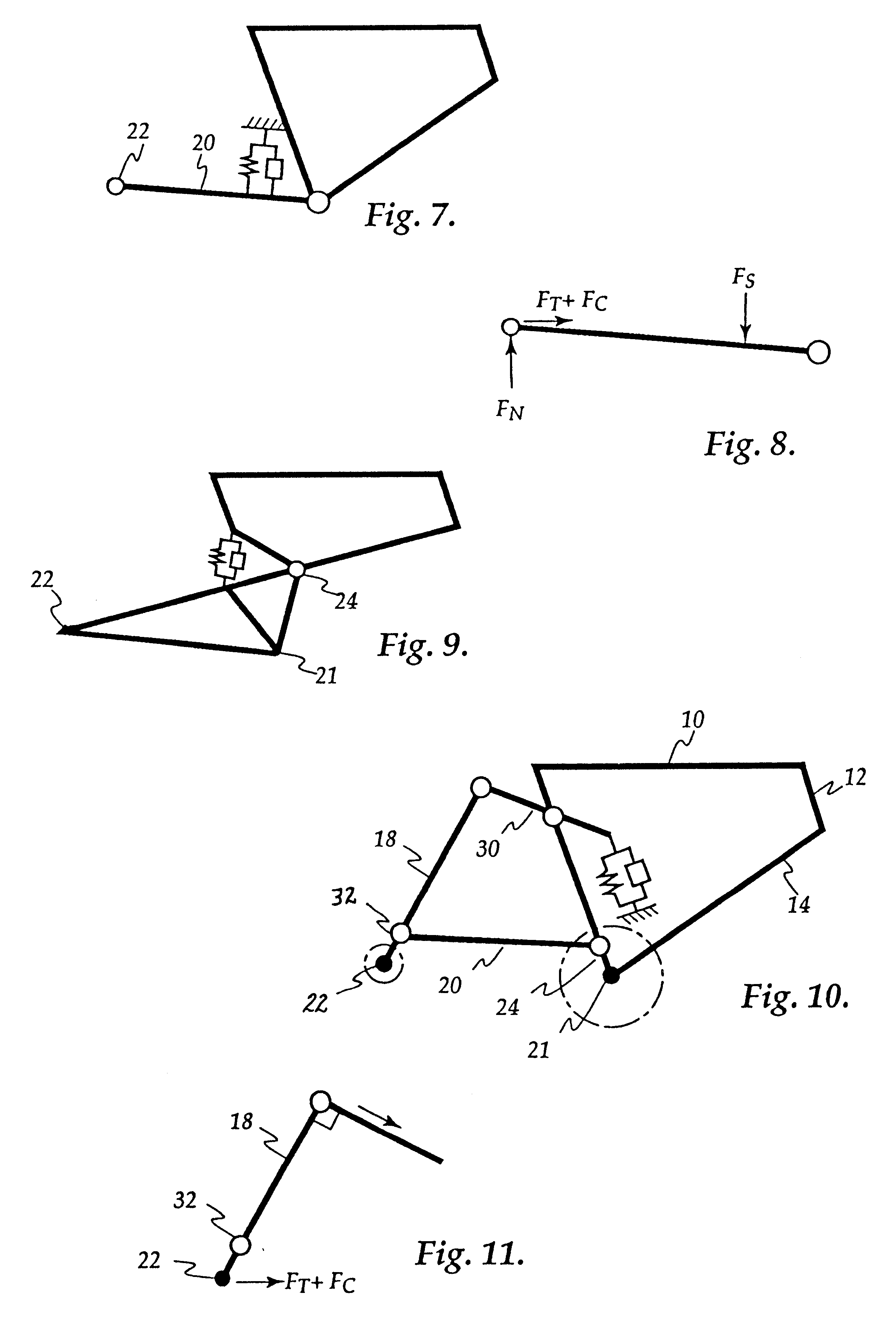
In FIG. 2 there is shown a high pivot design in which the chain stays 20 are pivotably mounted to the seat tube 16 at a point 24 well above the bottom bracket. As can be seen the seat stays 18 have been eliminated and, in this particular example, the spring / damper is mounted between the down tube and the forward end of the chain stays.

Referring to FIG. 3 there is shown a free body diagram of the chain stay 20 of the high pivot design.

With a rider sitting ...


PUM


Abstract

A rear suspension system for a bicycle is disclosed. The system includes a link member (30) and chain stay (20) each pivotably mounted to the sprung mass. The seat stay (18) mounts the rear axle (22) and is pivotably mounted at its upper end to link member (30) and is pivotably mounted at a point intermediate its length to chain stay (20).

Description

This invention relates to a rear suspension system for a bicycle.The two primary functions of a rear suspension system in a bicycle are to maintain tire contact with the ground during bumps and depressions and to isolate shock and vibration from the rider.Many different rear suspension systems are presently on the market. Known systems include the high pivot design, low / forward pivot design, bottom bracket pivot design, unified rear triangle design and numerous multi-link designs.A problem that all rear suspension designers have to address is the elimination of undesirable effects associated with rear suspension including those which have been loosely referred to by cyclists as "bio-pacing".In recent times there has been an attempt to quantify "bio-pacing" in terms of neutrality (N-factor) and pedal feedback (P-factor). Both factors are functions of suspension geometry and also vary with gear selection. When a cyclist refers to "bio-pacing" they are usually referring to pedal feedba...

Claims


Application Information

Patent Timeline
IPC IPC(8): B62K25/04B62K25/28
CPCB62K25/28B62K25/286
Inventor GUENTHER, PETER
Owner GUENTHER PETER
Why Eureka
Try Eureka