
Putter golf club with rearwardly positioned shaft

Inactive Publication Date: 2001-03-20
CALLAWAY GOLF CO
View PDF2 Cites 34 Cited by
  • Summary
  • Abstract
  • Description
  • Claims
  • Application Information

AI Technical Summary

Benefits of technology

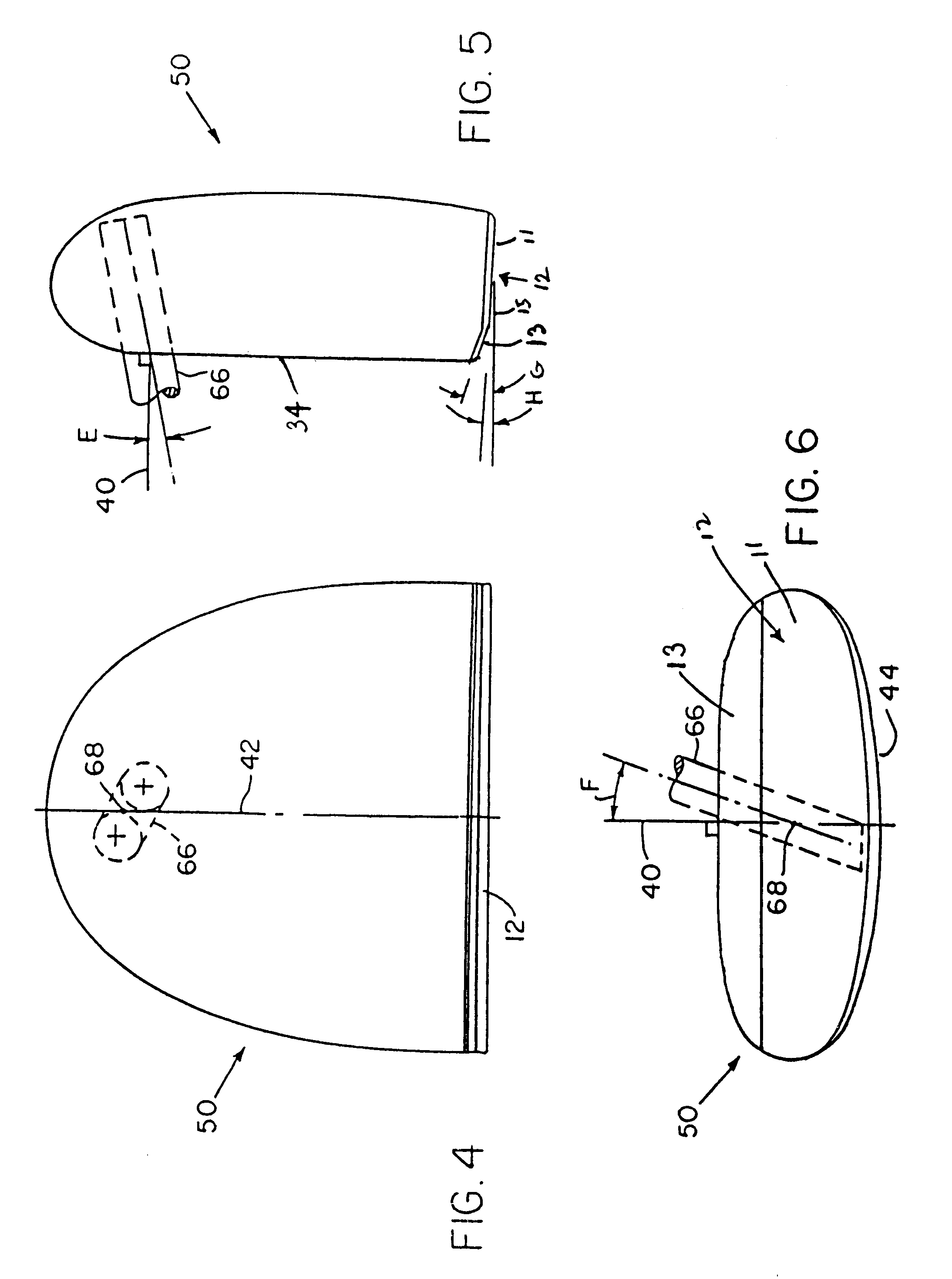
An elongated shaft can be utilized so that the end of the shaft distal from the head can be rendered essentially motionless by the application of force of the user's arm against the shaft and against the user's ribs. The putter face is angled as a single angle or as a compound angle by being angled at a bottom portion of the face toward the back edge at a first angle and at a top portion of the face toward the back edge at a second angle larger than the first angle. The putter embodiment of this invention having the compound angled face provides the user with a better view of the face and a ball in contact with the face as compared to a putter face having a single angle.
It has been found that the putter of this invention provides a larger sweet spot as compared to putters having a different shaft configuration and position. By positioning the shaft rearwardly of the majority of the weight of the head, the rearward portion of the putter including the shaft follows the forwardly positioned portion of the head weight. After motion of the putter has been initiated, the momentum of the moving forward portion of the head reduces the need for added force on the shaft by the user and thus reduces the opportunity for applying undesirable force direction to the shaft by the user. In addition, in one embodiment, the user of the putter of this invention is provided with an improved view of the position of a golf ball relative to the face for contacting the ball.

Problems solved by technology

When utilizing the required higher velocity, the user tends to lose control over the putting stroke.
In addition, with a light weight club head, the inertia of the ball and club head are similar so that when the ball contacts the club head slightly off-line from the center of mass of the club head, the club head tends to rotate thereby causing the ball to move away from the club head at an angle that deviates from the intended direction together with a spinning motion on the ball that further adversely influences the ball's path.
With a relatively low weight club head any small irregular motion on the part of the user produces a relatively large deviation in the club head velocity and direction which results in erratic puffing.
Another common problem among golfers is the inability to initiate a putting motion i.e., freezing during preparation for a putt, known in golfing terminology as the "yips".
This condition may result, in part from the sensitive nature of the putt and the appreciation that the slightest lack of control and the delicate putting motion will result in an unwanted result.

Method used


Image

  • Putter golf club with rearwardly positioned shaft
  • Putter golf club with rearwardly positioned shaft
  • Putter golf club with rearwardly positioned shaft

Examples


Embodiment Construction

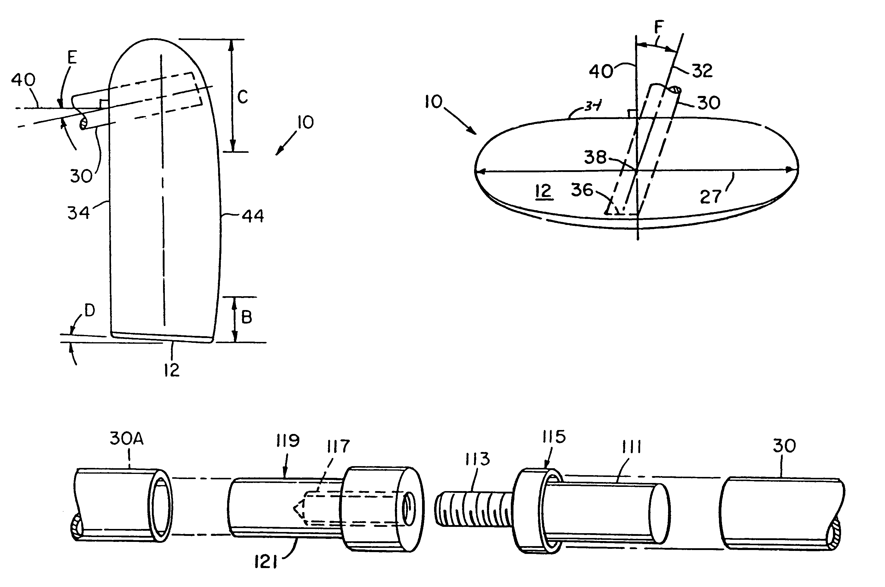
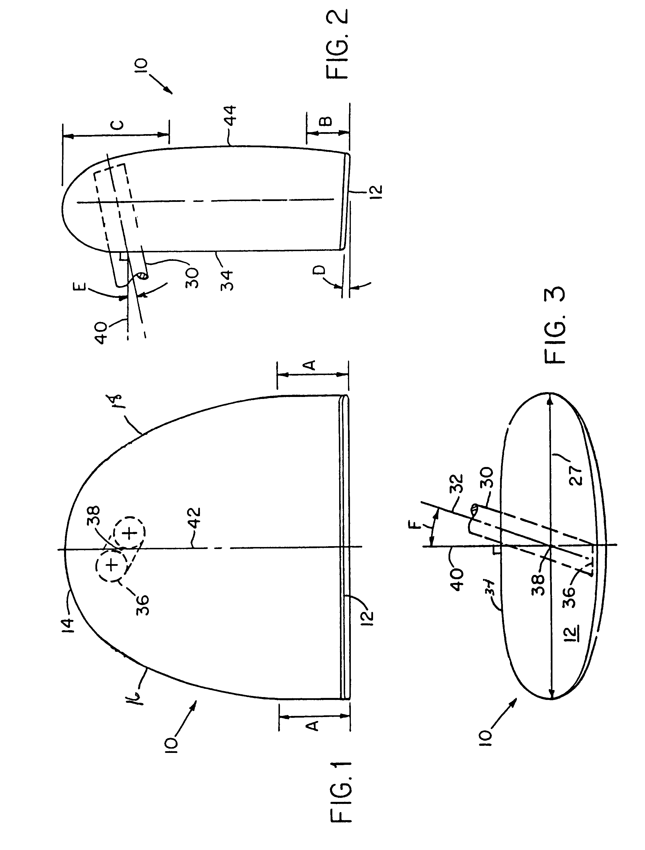
The putter of this invention has a mallet-like head having a front face which is used to contact the golf ball, a back edge, side edges, a top surface through which a shaft extends and a bottom surface. The back edge and side edges can be linear or curved. The head can be formed from any metal such as aluminum, aluminum alloy, steel, or brass or a non-metallic material such as a polymeric composition, e.g., polycarbonate, preferably aluminum or low density aluminum alloy. If desired, additional weight can be added to the putter head. The optional weights can be added to a surface of the putter head or can be embedded within the volume of the putter head in any conventional manner.

The shaft is positioned at least about 70%, preferably at least about 85% of the maximum length of the putter head away from the front face toward the back edge. By positioning the weight of the putter head forward of the shaft, certain advantages are obtained. First, by positioning the weight of the putter...


PUM


Abstract

A golf putter is provided having a head and shaft. The shaft enters the head at a point at least about 70% of the length of the putter away from the front face. The shaft is angled about 10° to about 20° toward the front face of the head and angled about 10° to about 20° toward a user grasping the shaft.

Description

1. Field of the InventionThis invention relates to a putter golf club (putter). More particularly, the present invention relates to a putter with a head having a shaft positioned at a rearward portion of the head relative to the front face of the putter.2. Description of Prior ArtAt the present time, there are available a wide variety of putters which are golf clubs designed for striking a golf ball on substantially smooth grass portions of a golf course known as "putting greens". Since putting accounts for approximately one half of the golf strokes which a normal golfer takes during a round of golf, it is particularly important that the putter be designed to permit an accurate putting stroke.The most common putter design at the present time is some variation of a simple relatively light weight "blade" on the end of a relatively short shaft as exemplified by U.S. Pat. No. 4,429,875. A blade type putter is relatively low weight club which requires the user to strike the ball with a h...

Claims


Application Information

Patent Timeline
IPC IPC(8): A63B53/02A63B53/10A63B53/04A63B59/00A63B53/12
CPCA63B53/02A63B53/0487A63B53/10A63B53/12A63B59/0014A63B59/004A63B2053/0441A63B59/0074A63B2053/021A63B2053/0408A63B2053/0491A63B2210/50A63B59/0055A63B60/06A63B60/08A63B60/10A63B60/20A63B60/34A63B60/42A63B53/021A63B53/0408A63B53/0441
Inventor COLLINS, CLARK E.
Owner CALLAWAY GOLF CO
Learn More