Modular system for shaft prostheses

a technology of modular system and shaft, applied in the field of modular system, can solve the problem of requiring a surgeon to consider spatial imagination

Inactive Publication Date: 2001-03-20
ZIMMER GMBH
View PDF33 Cites 148 Cited by
  • Summary
  • Abstract
  • Description
  • Claims
  • Application Information

AI Technical Summary

Problems solved by technology

A disadvantage of this arrangement is that this setting of the inclination must be do

Method used


Image

  • Modular system for shaft prostheses
  • Modular system for shaft prostheses
  • Modular system for shaft prostheses

Examples


Embodiment Construction

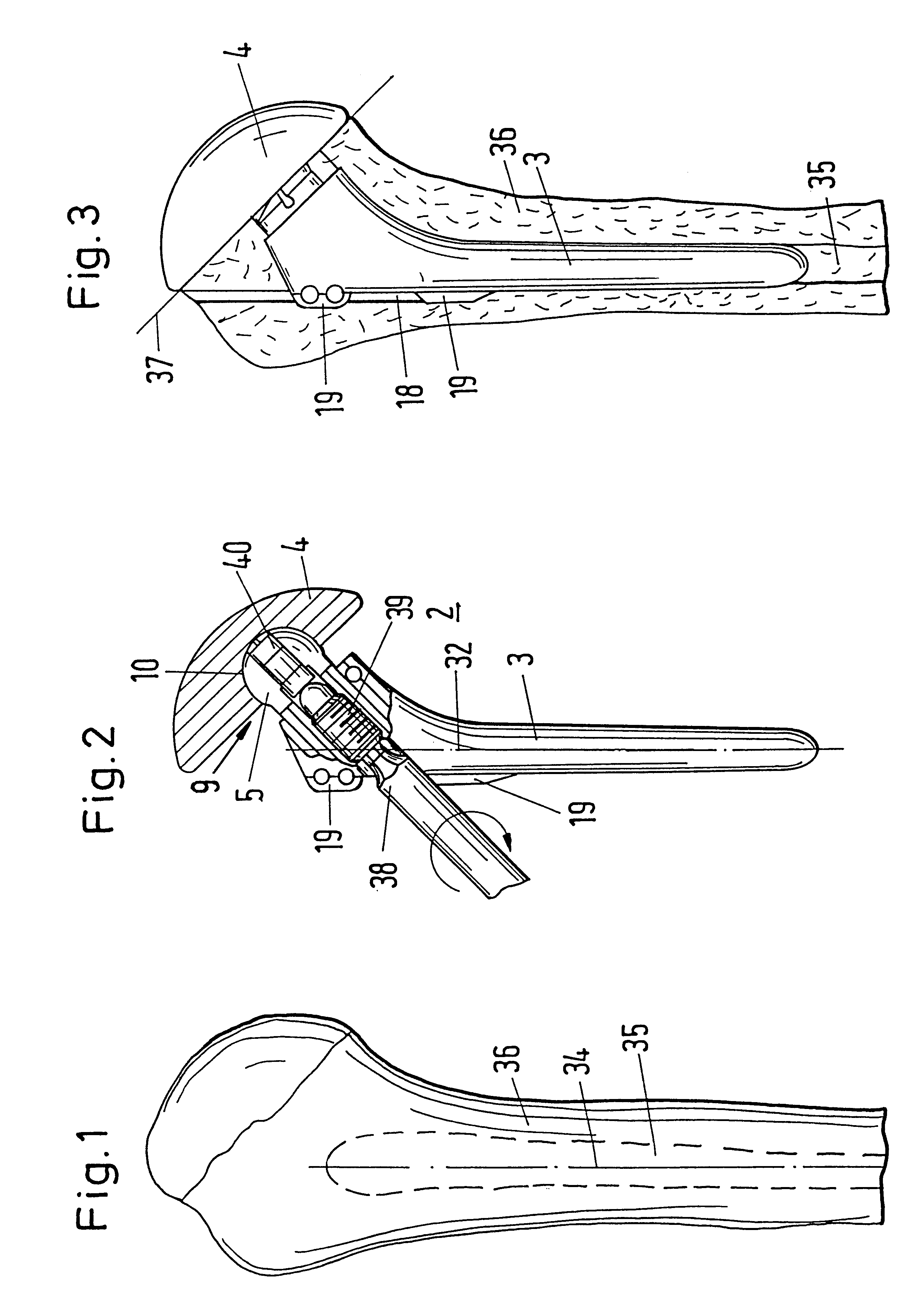
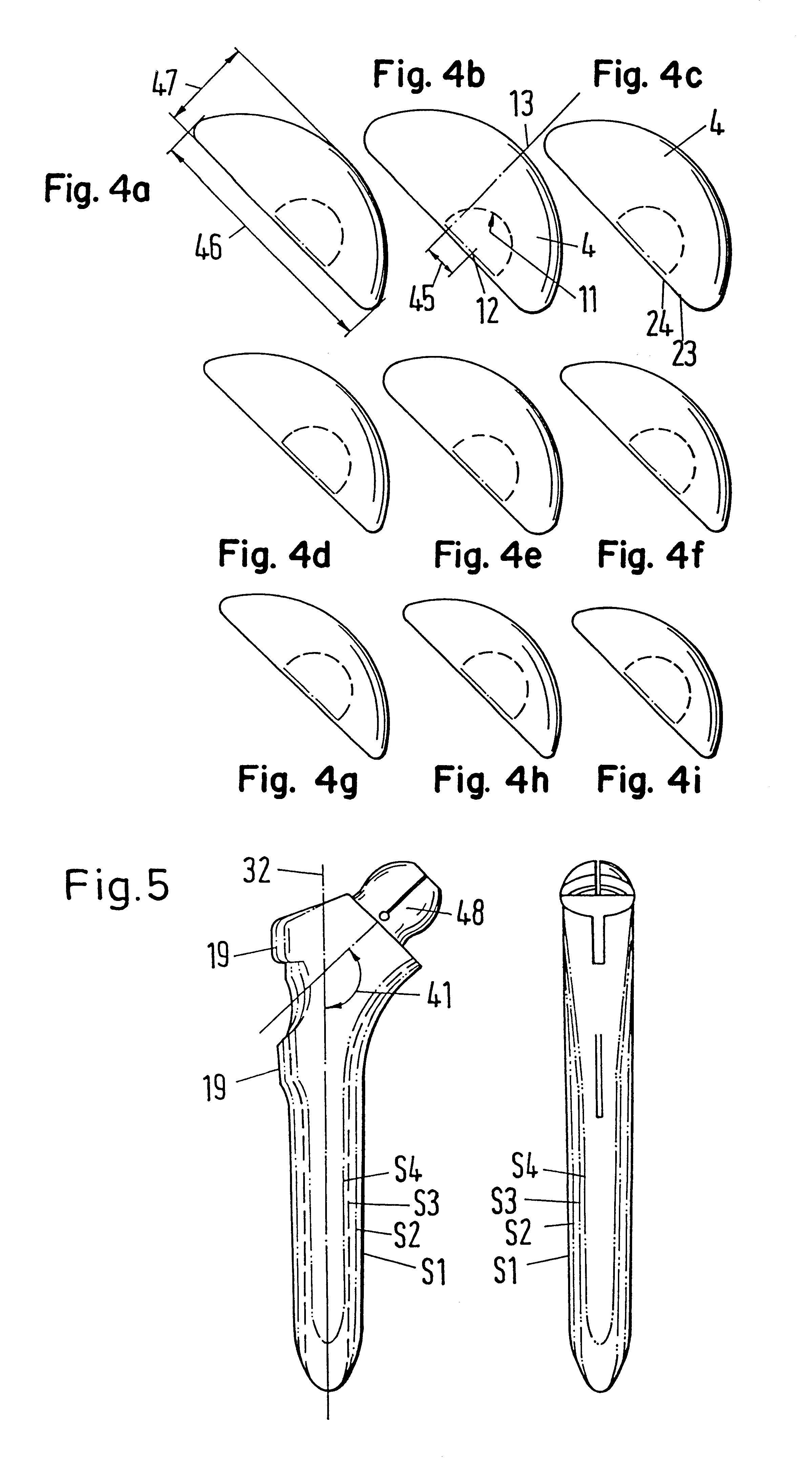
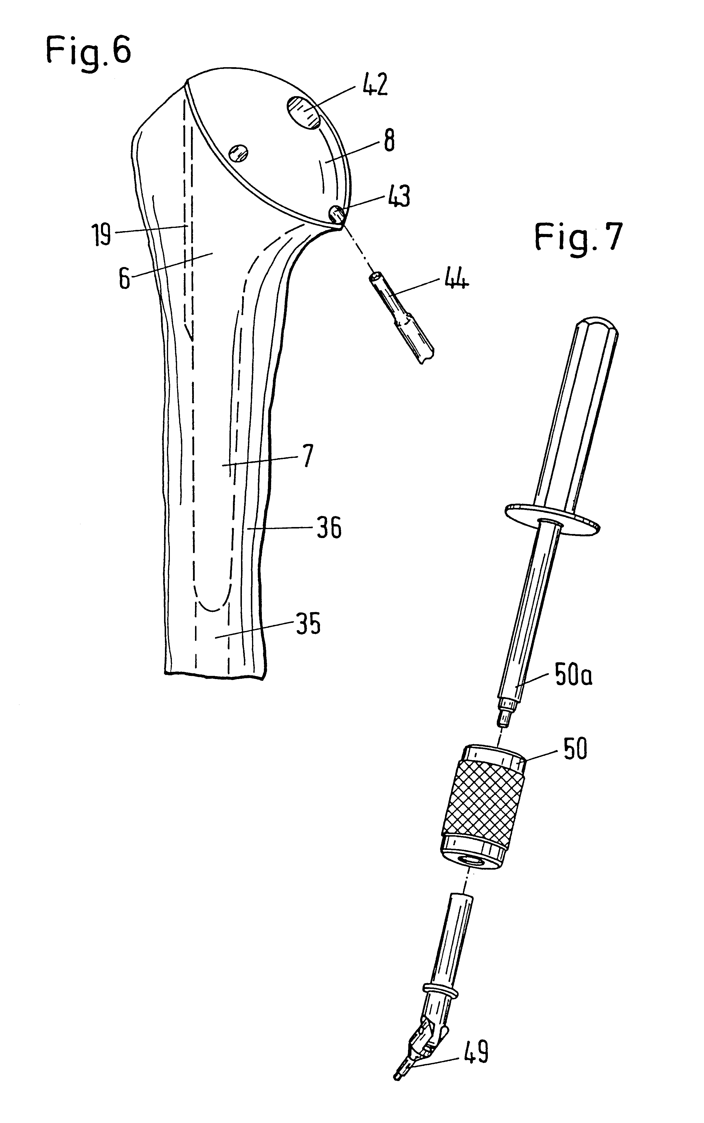
The figures show a modular system for the monitoring of shaft prostheses which have a coupling between the prosthesis stem 3 and the prosthesis head 4 which can be fixed in a predetermined angular range and which can be fixed through an apparatus in the prosthesis stem 3. Through a modular system with combinable stems and prosthesis heads of different sizes and prostheses 3, 4 and test prostheses which are constructionally similar outwardly and in the location of the points of rotations, a large variety of test prostheses and shaft prostheses arises. The test prostheses have an apparatus in the prosthesis head which permit the fixing of the head in an ideal position with testable function when a stem is inserted into a bone. This position between the head and the stem is preserved when extracting the test prosthesis and transferred to a mounting apparatus 1 in which a shaft prosthesis 3, 4 which is built up of analogous parts is brought into the same position and fixed.

FIGS. 1 to 5 ...


PUM


Abstract

With the invention a modular system for the mounting of shaft prostheses is shown which have a coupling which can be fixed within a predetermined angular range between the prosthesis stem and the prosthesis head, which can be fixed by an apparatus in the prosthesis stem. Through a modular system with combinable stems and prosthesis heads of differing sizes for prostheses and test prostheses which are constructionally alike externally and in the position of the point of rotation, a variety of test prostheses and shaft prostheses arises. The test prostheses have an apparatus in the prosthesis head which permit the fixing of the head in an ideal position with a controllable function in a stem inserted in a bone. This position between the head and the stem is preserved when the test prosthesis is extracted and transferred to a mounting apparatus, in which a shaft prosthesis which is built up of analogous parts is brought into the same position and fixed.

Description

1. Field of the InventionThe present invention relates to a modular system with a mounting apparatus for the mounting of shaft prostheses.2. Description of the Prior ArtFR-A-2 727 857 shows a shaft prosthesis for a shoulder joint which consists of a stem and a prosthesis head which are connected to one another via a fixable ball joint. The prosthesis head consists of a shallow spherical section, the underside of which is to lie on a planar resection surface of a humerus in order to completely cover off the resection surface. A spherical body which stands off from the stem in an inclined direction to the stem axis is divided up by slits into lobes which can be spread apart by a thorn which is driven into the spherical body through the stem in the inclined direction. In the prosthesis head a spherical bearing shell is worked in from the lower side which encloses the spherical body during the spreading apart and blocks it at a selectable angle to the stem axis. A disadvantage of this a...

Claims


Application Information

Patent Timeline
IPC IPC(8): A61F2/30A61F2/40A61F2/46A61B17/88A61F2/02A61F2/00
CPCA61F2/40A61F2/4637A61F2/4684A61B17/8875A61F2/4059A61F2002/30378A61F2002/30484A61F2002/30507A61F2002/30538A61F2002/3054A61F2002/30596A61F2002/30598A61F2002/30616A61F2002/30617A61F2002/30772A61F2002/30774A61F2002/30797A61F2002/30884A61F2002/4018A61F2002/4037A61F2002/4062A61F2002/4619A61F2002/4623A61F2002/4641A61F2002/4668A61F2002/4681A61F2220/0025A61F2220/0033A61F2250/0006A61F2250/0097A61F2310/00011A61F2002/30594A61F2/4603
Inventor FAREY, SAMUEL
Owner ZIMMER GMBH
Why Eureka
Try Eureka