
Modular video conference enclosure

a video conference enclosure and module technology, applied in the field of remote telecollaborative conferencing, can solve the problems of limited two-way video conferencing users, inconvenient transportation of video conferencing rooms, and limited access to the public at large to video conferencing systems

Inactive Publication Date: 2001-03-27
PELTZ DIANE P
View PDF30 Cites 288 Cited by
  • Summary
  • Abstract
  • Description
  • Claims
  • Application Information

AI Technical Summary

Benefits of technology

A further object of the invention is to provide a secure, modular and movable interactive two-way telecollaborative video conferencing and imaging enclosure for conducting business or privileged medical, legal, or other confidential matters in private, being particularly equipped for remote monitoring of physiological attributes of one or more users by medical specialists and remote interaction between users and medical specialists.
This invention provides two-way interactive video conferencing, and has a preferred embodiment of the enclosed units being transportable. For instance, the preferred embodiment of the shelters are modular, with the design easily broken down into transportable pieces fitting through regulation size house doors for moving and assembling. The transportability of the smaller shelters allows for the shelters to be moved to other locations and not be left stationary as part of a room, such as in a video conferencing room The larger embodiments of the invention are transportable and can be placed on flat bed units, moved over the road via tractor-trailer or built as a railroad car shelter.

Problems solved by technology

While open communication kiosk solutions are in wide-use for public informational use, most, if not all of these kiosks are of an open design, with at least one wall missing allowing for limited privacy for users conducting personal or confidential business matters.
Yet, the public at large has little accessibility to a video conferencing system.
This is limiting as the user can be heard, but generally not seen on the remote end.
Most often, users of two-way video conferencing are limited to conducting point-to-point meetings, or multipoint meetings, from a desktop computer, or from a roll-about room unit, or from an open three sided kiosks, or from a dedicated boardroom or conferencing room.
Video conferencing rooms, while closed and allowing for privacy, are not transportable.

Method used


Image

  • Modular video conference enclosure
  • Modular video conference enclosure
  • Modular video conference enclosure

Examples


Embodiment Construction

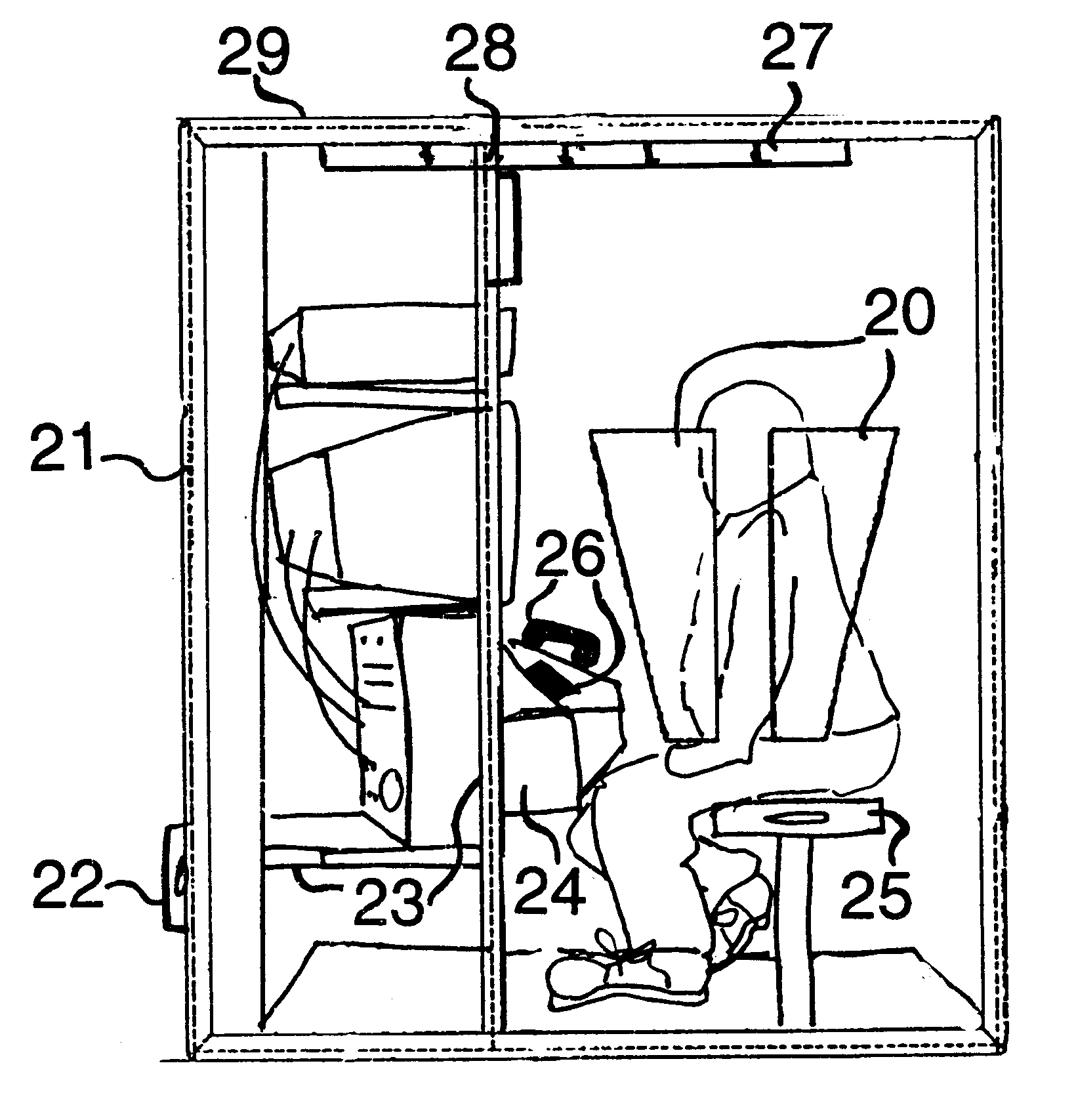
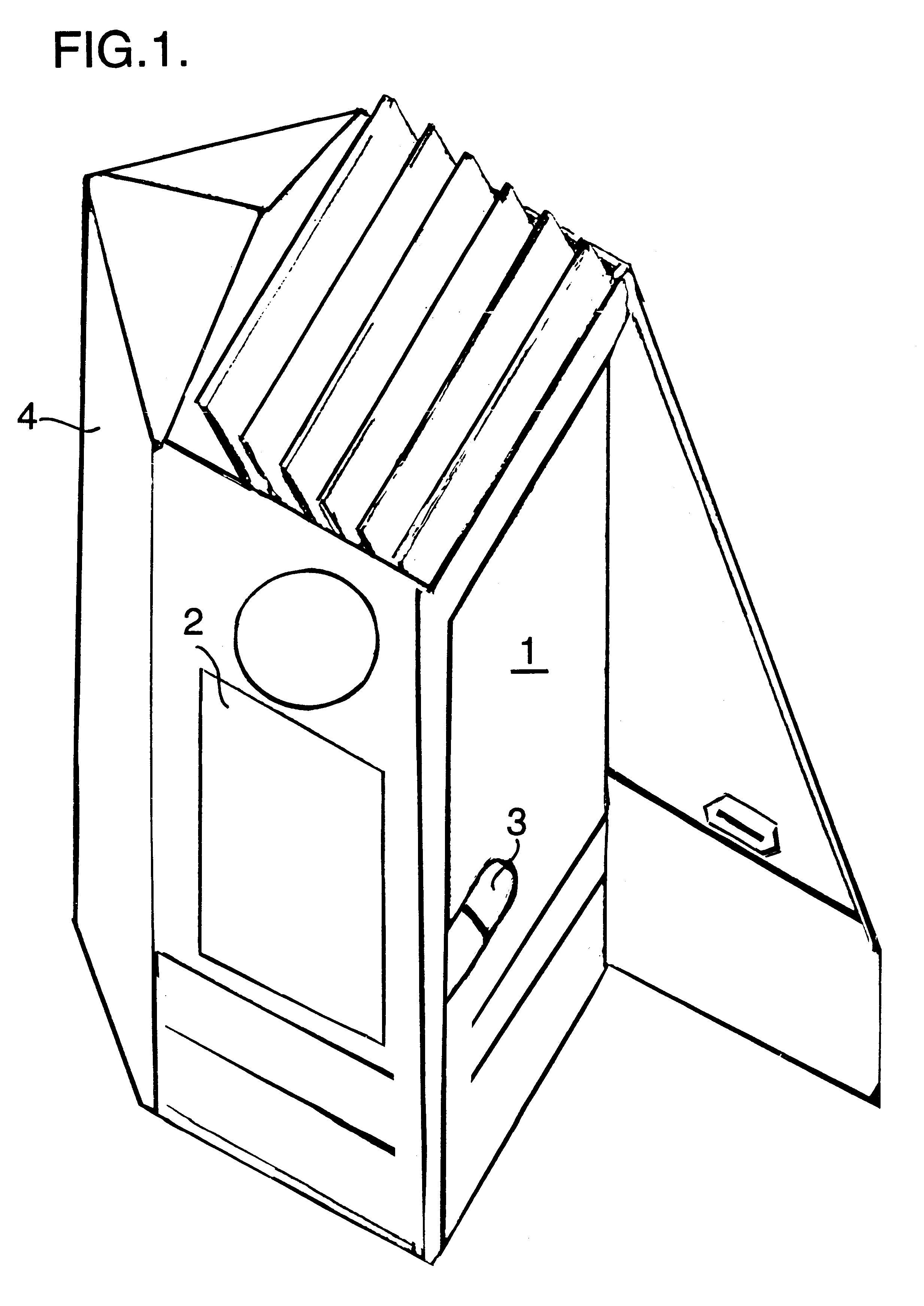
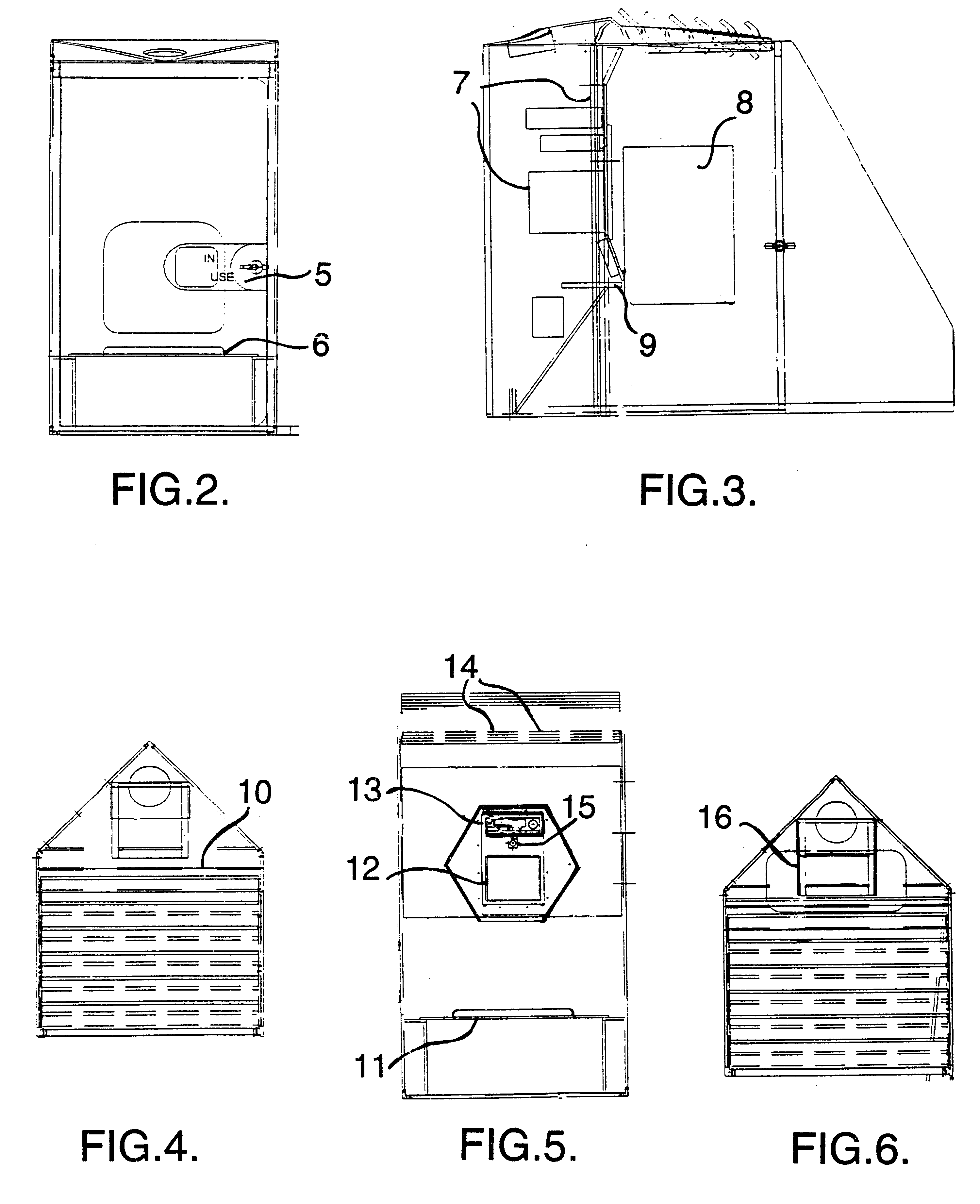
Referring now to the drawings, and more particularly to FIGS. 1 through 12, there is shown implementation of the invention in three prototypes. FIGS. 1 through 6 show Prototype One. FIG. 1 is an artist perspective rendering of an embodiment designed for one-person. It shows a wheelchair accessible door (1), windows (2), smart card or credit card access (3), and in-use sign and locked equipment storage cabinet (4). FIG. 2 is a front view showing in-use sign (5) and seat (6). FIG. 3 is a back wall and window view showing equipment stacking rack (7); rectangular window design (8); touch screen and telephone console (9) attached to front of firewall. FIG. 4 is a top view showing a vented top roof (10) design. FIG. 5 is a view from inside the enclosure showing conferencing on a monitor; the seat position (11); a video conferencing monitor (12); a Video Cassette Recorder (VCR)(13); some vents in roof (14), and a camera mount (15). FIG. 6 is a top view with a rack and stack unit (16) in th...


PUM


Abstract

A secure, modular and movable interactive two-way telecollaborative video conferencing and imaging enclosure for conducting business or privileged medical, legal, or other confidential matters in private, being particularly equipped for remote monitoring of physiological attributes of one or more users by medical specialists and remote interaction between users and medical specialists.

Description

1. Field of the InventionThe present invention generally relates to remote telecollaborative conferencing and in particular to modular and secure enclosures equipped therefore.2. Background DescriptionThis invention relates to the fields of booths, kiosks, or shelters, and conducting two-way interactive videoconferencing from inside enclosed shelters. While open communication kiosk solutions are in wide-use for public informational use, most, if not all of these kiosks are of an open design, with at least one wall missing allowing for limited privacy for users conducting personal or confidential business matters.Today two-way video conferencing is commercially readily available. Yet, the public at large has little accessibility to a video conferencing system. When public accessibility is available, it is generally from an open kiosk with little or no privacy from the people standing near you while you transact your business. If kiosks offer video conferencing opportunities, most of ...

Claims


Application Information

Patent Timeline
IPC IPC(8): E04H1/12H04N7/14H04M11/00
CPCE04H1/125H04M11/00H04N7/142Y10S345/905G16H80/00
Inventor PELTZ, DIANE P.
Owner PELTZ DIANE P
Learn More