Apparatus and method for sampling fluid from reactor vessel

a technology for fluid sampling and reactor vessels, applied in the direction of sampling, measurement devices, instruments, etc., can solve the problems of waste of often expensive chemicals being mixed in reactor vessels, unmixed samples, time-consuming and inconvenient processes, etc., and achieve the effect of convenient and reliable sampling

Inactive Publication Date: 2001-03-27
PROSYS SAMPLING SYST
View PDF6 Cites 35 Cited by
  • Summary
  • Abstract
  • Description
  • Claims
  • Application Information

AI Technical Summary

Benefits of technology

An object of the present invention is to provide an improved fluid-sampling apparatus which easily and reliably gives properly-representative samples from a reactor vessel.

Problems solved by technology

However, numerous disadvantages and shortcomings exist with prior systems, and there is a need for improvement to overcome such disadvantages and shortcomings.
The above-described sampling system has drawbacks in that the sample fluid volume would consist of partial previous sampling fluid if the system is not purged after each sampling, or would nonetheless consist of the first volume of fluid that is drawn from the top of the tank without any system fluid flushing first.
Such sampling system can only get an unmixed sample within the sampling bottle by drawing numerous cycles of fluid through the system.
This is a time-consuming and inconvenient process, and is wasteful of the often expensive chemicals being mixed in the reactor vessel.
However, the Neotecha systems have the problem that, when chemical compositions in the reactor vessel have particulates or become viscous to some extent, the compositions can tend to clog or damage the pump.
This leads to costly down time for cleaning and repair.
These and other existing devices for sampling fluids from reactor vessels have significant problems.

Method used


Image

  • Apparatus and method for sampling fluid from reactor vessel
  • Apparatus and method for sampling fluid from reactor vessel
  • Apparatus and method for sampling fluid from reactor vessel

Examples


Embodiment Construction

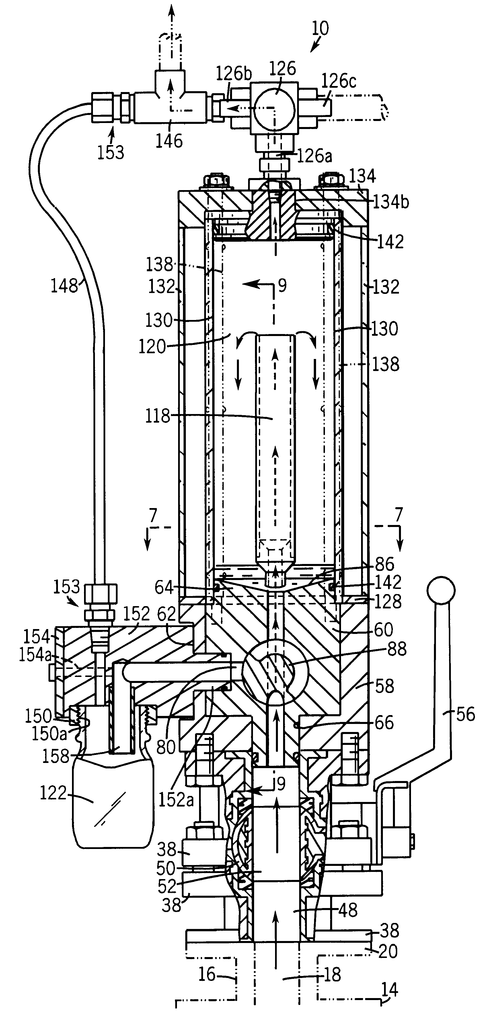
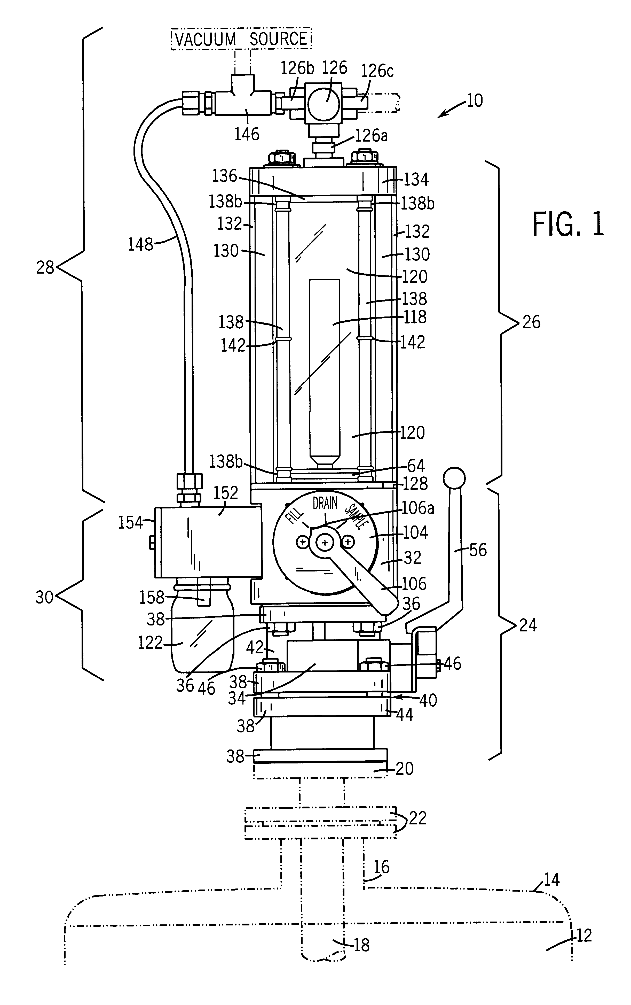
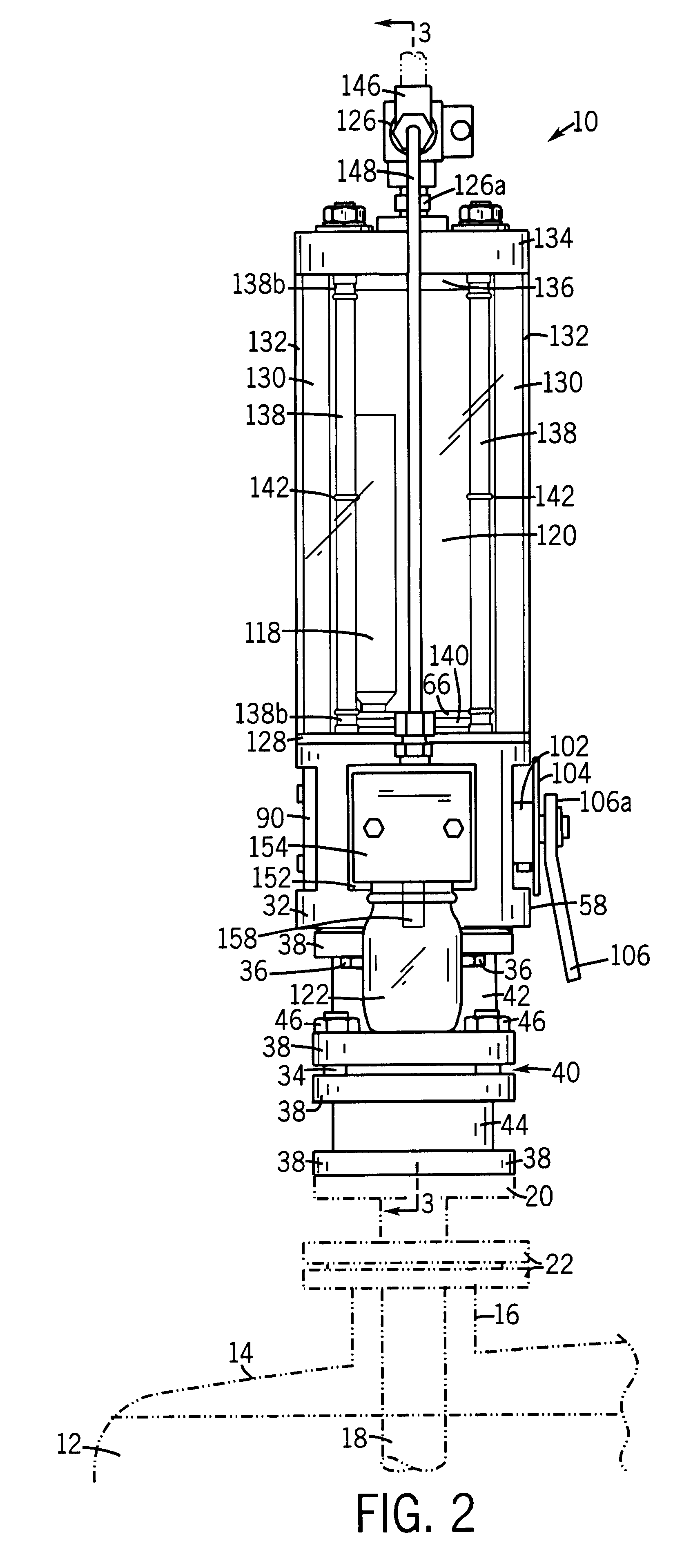
FIGS. 1 and 2 illustrate a fluid-sampling apparatus 10 for sampling fluid 12 from a reactor vessel 14. Fluid-sampling apparatus 10 is mounted on top of a sampling port 16 of reactor vessel 14. A dip tube 18, having either a single flange 20 or a double flange 22 (as denoted in dashed outline) at the top thereof, is connected to the bottom of fluid-sampling apparatus 10. Dip tube 18 extends through sampling port 16 of reactor vessel 14 into fluid 12 at the top of reactor vessel 14.

Fluid-sampling apparatus 10 includes: a valve assembly 24; a overflow chamber assembly 26; a vacuum assembly 28; and a sample bottle mounting assembly 30. Each of valve assembly 24, overflow chamber assembly 26, vacuum assembly 28, and sample bottle mounting assembly 30 is comprised of various component parts which will be explained below.

Valve assembly 24 includes a sampling valve 32 mounted on top of a ball valve 34. The bottom of sampling valve 32 is connected to the top of ball valve 34 via mating faste...


PUM

PropertyMeasurementUnit
angleaaaaaaaaaa
diameteraaaaaaaaaa
angleaaaaaaaaaa

Abstract

A fluid-sampling method and apparatus are disclosed. The apparatus includes a valve assembly, an overflow chamber assembly, a vacuum assembly and a sample bottle mounting assembly in particular arrangements. In certain preferred embodiments the overflow chamber assembly has an inner vessel, preferably a standpipe, within an outer vessel which forms an overflow chamber in which fluid from the standpipe can be viewed. The valve assembly preferably includes a sampling valve with an outer shell, an insert member and a pivotable valve member therein. The pivotable valve member preferably has a main body portion with first and second circumferential grooves therein and a diagonal bore therethrough for properly directing fluid from and through particular ports in the insert member based on the position of the valve member. The method includes drawing the fluid from the reactor vessel through a valve assembly into an inner vessel of an overflow chamber assembly, overflowing the fluid from the inner vessel into an outer vessel of the overflow chamber assembly, and thereafter retrieving a sample from the inner vessel.

Description

The present invention generally relates to the sampling of fluid for testing and, more particularly, to apparatus and methods for periodically sampling fluids from reactor vessels while reactions are in progress.A variety of systems for sampling fluids from reactors and tanks are known. However, numerous disadvantages and shortcomings exist with prior systems, and there is a need for improvement to overcome such disadvantages and shortcomings.Some examples of commercially-available prior fluid-sampling devices are the "Safesamp Reactor Sampling Systems" sold by Technova AG, of Sweden, and the "Neotecha Sampling Systems" sold by Grinnell Corporation, of Exeter, N.H.The Safesamp system's basic arrangement includes a flanged dip pipe for connection to the tank with the dip pipe extending downwardly into the fluid in the tank, a bottom flange with a suction hose mounted at the top and extending downward through the dip pipe and into the tank fluid and a perpendicular connection port in ...

Claims


Application Information

Patent Timeline
Patent Type & Authority Patents(United States)
IPC IPC(8): G01N1/14G01N1/20
CPCG01N1/14G01N2001/1427G01N2001/205G01N2001/2071
Inventor SCHADT, JOHN C.ROMMELFAENGER, EUGENE R.FARRELL, MICHAEL D.
Owner PROSYS SAMPLING SYST
Why Eureka
Try Eureka