Golf club and weighting system

Inactive Publication Date: 2001-04-03
CALLAWAY GOLF CO
View PDF148 Cites 285 Cited by
  • Summary
  • Abstract
  • Description
  • Claims
  • Application Information

AI Technical Summary

Problems solved by technology

Although supplying the desired performance enhancements, the high density block and the reciprocal recess must be machined to precise tolerances, involving high production costs.
One drawback of this type of processing is the requirement that one must operate below the melt or softening temperature of the club head material.
In addition, as processing temperatures increase the associated costs will increase to accommodate higher energy use and high temperature equipment.
The limitations for a low melt temperature, yet high density, material

Method used


Image

  • Golf club and weighting system
  • Golf club and weighting system
  • Golf club and weighting system

Examples


Example

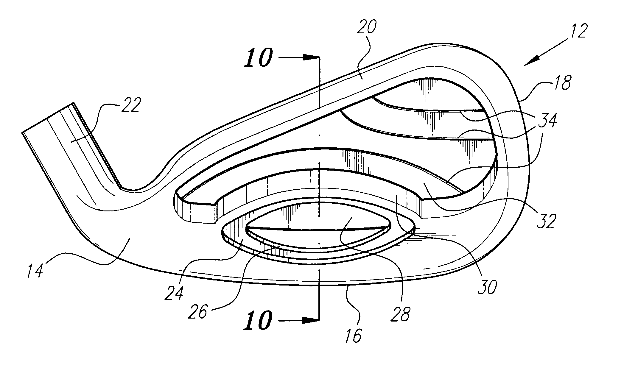
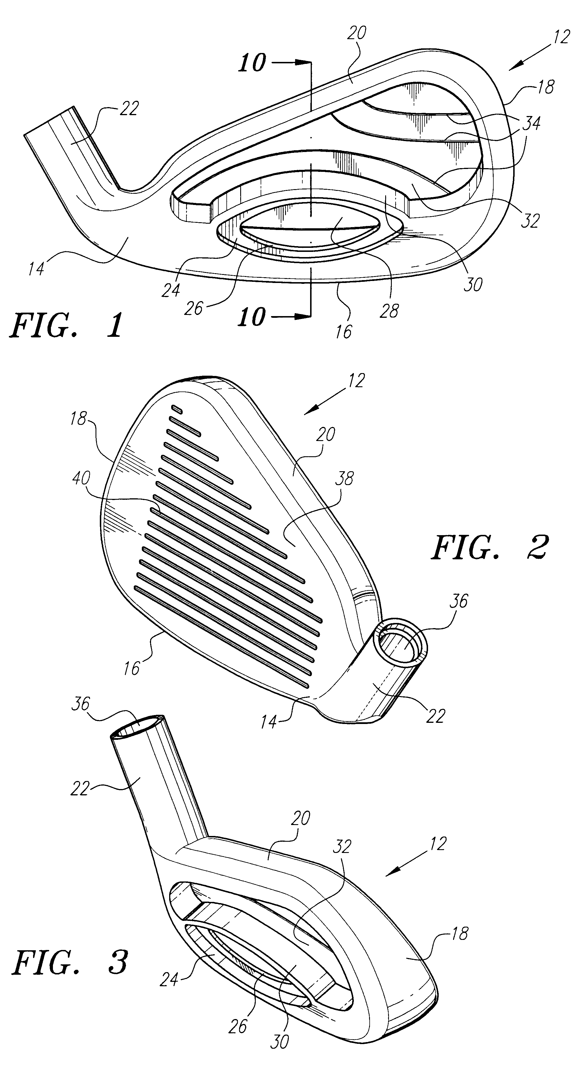
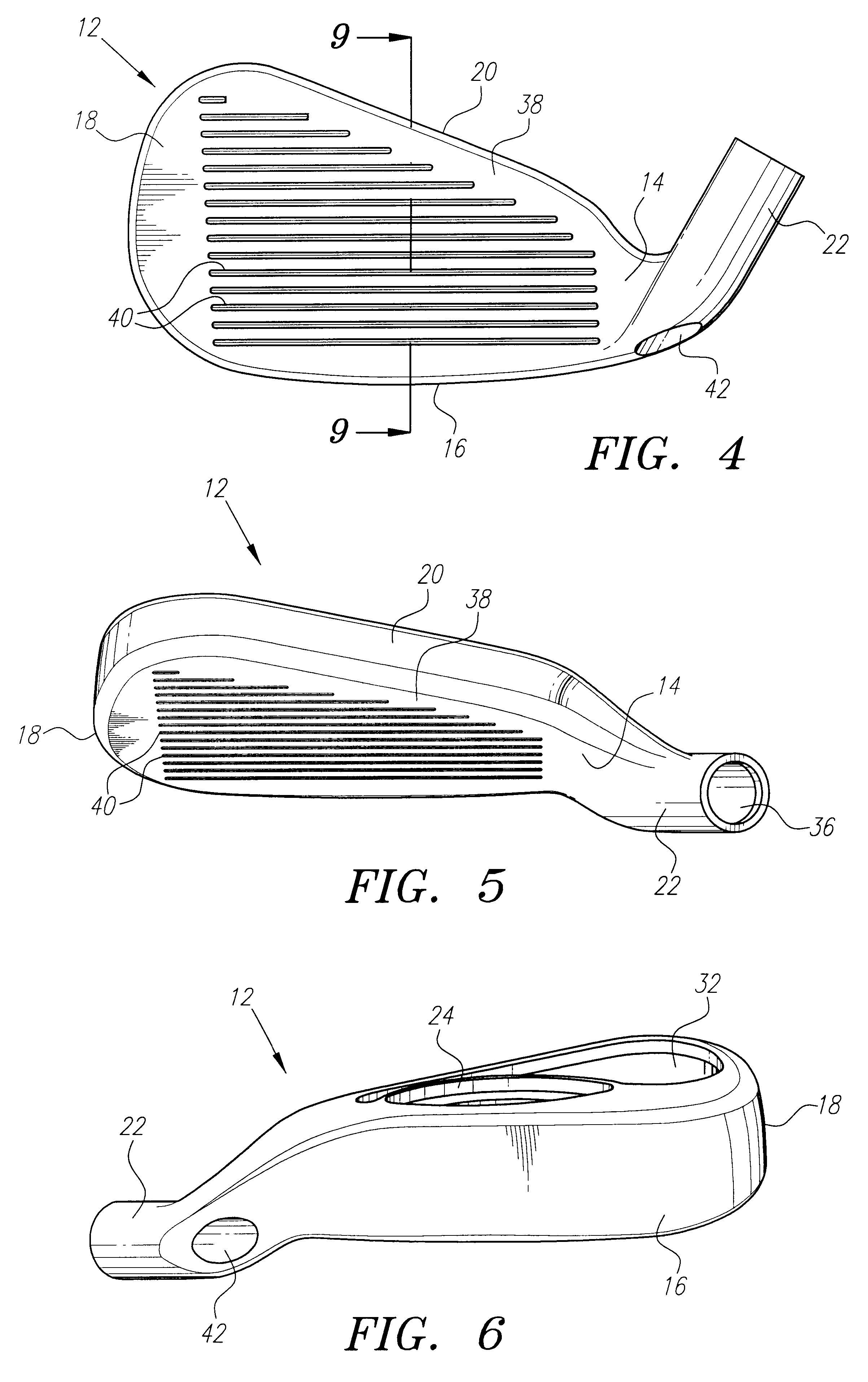
Like numbers are used throughout the detailed description to designate corresponding parts of a golf club head and a bi-material weight of the present invention.

As shown in FIGS. 1-8 a golf club of the present invention is generally designated 12. The golf club head 12 comprises a heel section 14, a bottom section 16, a toe section 18, a top section 20 and a hosel 22. The heel, toe, bottom and top sections, 14, 18, 16 and 20 respectively, are meant to describe general sections of the golf club head 12 and may overlap one another. The golf club 12 further comprises an inset wall 24, an entry 26, an internal cavity 28, a cavity flange 30, a rear face 32 and a series of contour lines 34 extending generally from the heel section 14 to the toe section 18. The internal cavity 28 is located within the rear flange 30, and generally extends adjacent the bottom section 16 from the heel section 14 to the toe section 18. In a preferred embodiment, a heel wall 44 (shown in phantom in FIG. 1) and...


PUM


Abstract

A golf club head having a defined internal cavity, and a golf club head containing a bi-material weight having a nonhomogeneous structure. A method to add the bi-material weight to the golf club entails heating, vibration and cooling to produce the nonhomogeneous structure.

Description

Not applicableNot applicable1. Field of the InventionThe present invention relates to golf clubs and, more specifically, a golf club head and weighting method to provide better performance, greater weighting flexibility and lower production costs.2. Description of the Related ArtThe location and distribution of weight within a golf club is an important factor in the performance of the golf club. In particular, weight placement at the bottom of the golf club head provides a low center of gravity to help propel a golf ball into the air during impact, and weight concentrated at the toe and heel of the golf club head provides a resistance to twisting, or high moment of inertia, during golf ball impact. Both the low center of gravity and high moment of inertia are important performance variables which affect playability and feel of the golf club. Alternative designs have resulted in many innovations for varying the weight location and distribution in a golf club head portion. Among these...

Claims


Application Information

Patent Timeline
IPC IPC(8): A63B53/04A63B53/06
CPCA63B53/04A63B53/047A63B53/0487A63B2053/0491Y10T29/53657A63B53/0466Y10T29/53535A63B2209/00A63B53/0416A63B60/02A63B2102/32A63B60/00
Inventor ERICKSON, JOEL B.GUARD, JOHN G.DOOLEY, JAMES F.PIMENTEL, M. GRACE HOHNDIMARCO, THOMAS J.
Owner CALLAWAY GOLF CO
Why Eureka
Try Eureka