Planar flow display method

a flow display and flow display technology, applied in the field of flow display methods, can solve the problems of inconvenient handling of actual numerical data, unsuitable representation,

Inactive Publication Date: 2001-04-03
KOTARO FUKUDA SHIGEO OHTSUKI & MOTONAO TANAKA
View PDF4 Cites 13 Cited by
  • Summary
  • Abstract
  • Description
  • Claims
  • Application Information

AI Technical Summary

Problems solved by technology

Although the above description has been made of the apparatuses observing the flow by use of the Doppler method by way of example, other general systems for the display of the flow such as fluid simulation systems have also not provided a display of the flow in the two-dimensional planar area defined in a three-dimensional flow in the form of inclusion of the state of the three-dimensional inflow and outflow.
It is to be noted that a streamline representative of a three-dimensional flow results naturally in a three-dimensional curve and hence is not suitable for representing a flow in a two-dimensional plane without any additional measures.
This is inconvenient for dealing with actual numerical data.

Method used


Image

  • Planar flow display method
  • Planar flow display method
  • Planar flow display method

Examples


Embodiment Construction

]

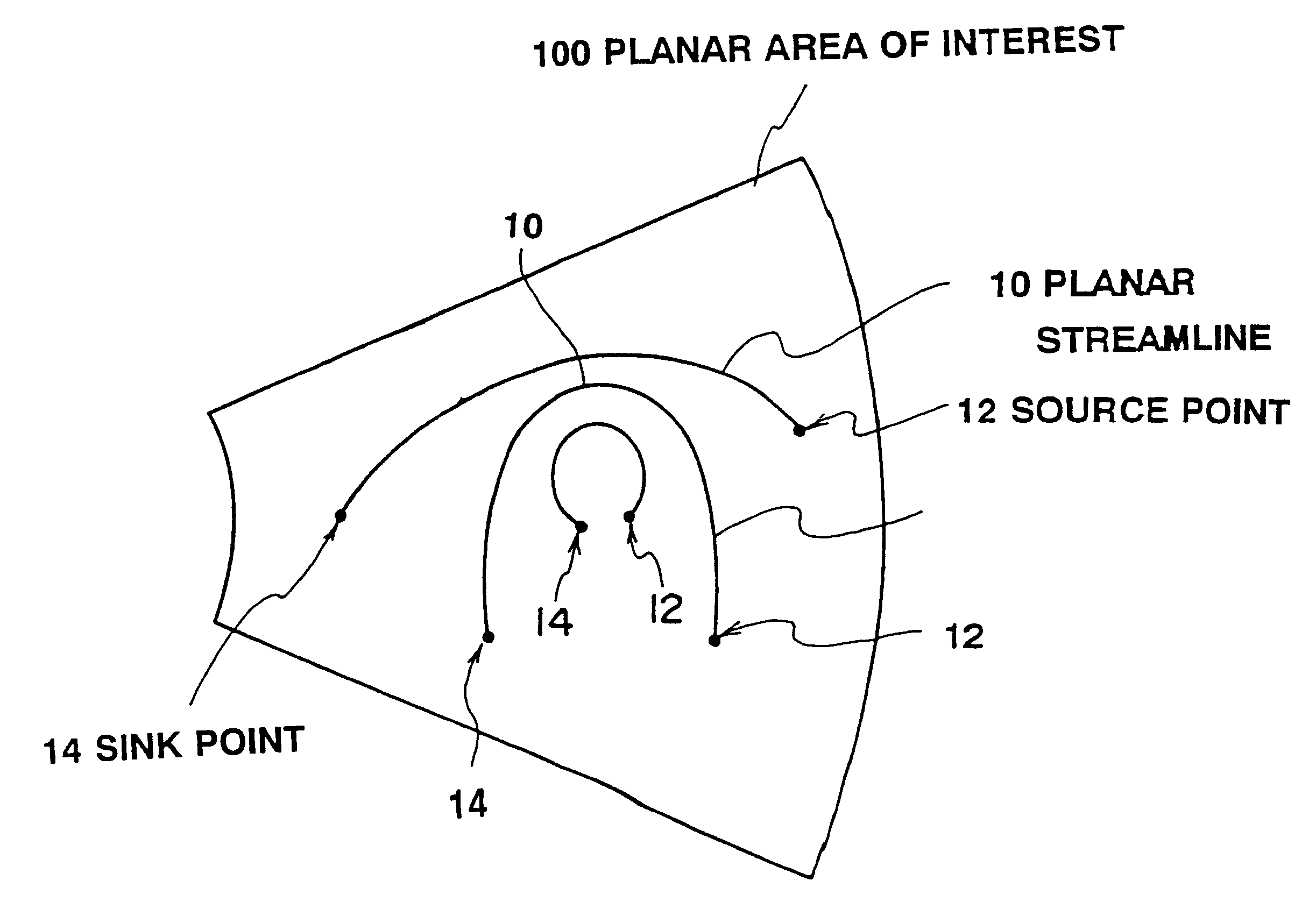
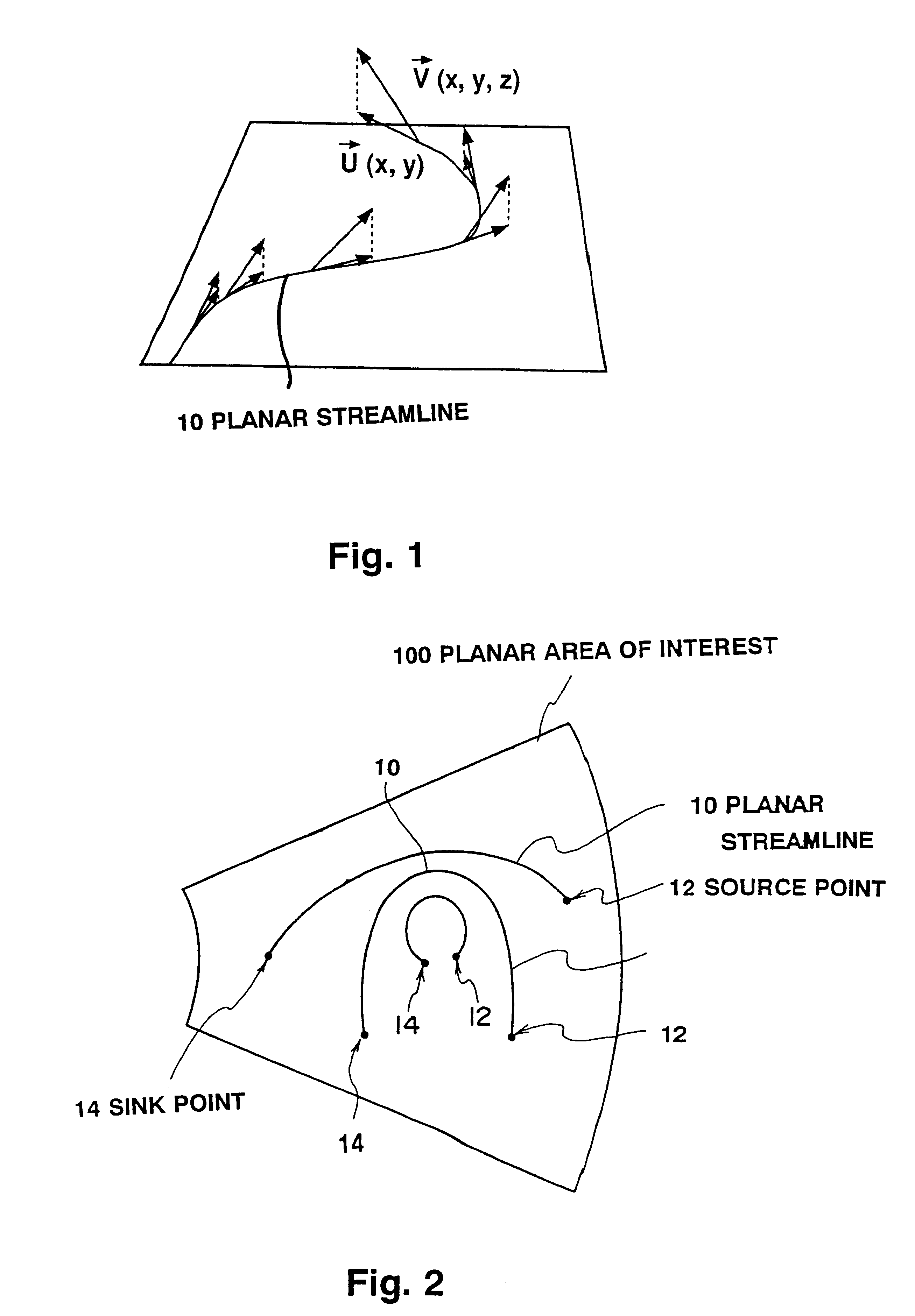
The planar flow display method in accordance with the present invention has been described hereinabove, taking the ultrasonic Doppler diagnostic apparatus as its major example. As is apparent from the above description, the invention is not limited to the ultrasonic Doppler diagnostic apparatus, but instead is applicable to, e.g., the numerical simulation or other display of the state of the planar area of interest in the three-dimensional flow field obtained by other various apparatuses and methods. That is, the method of this embodiment is applicable as long as the velocity profile of the flow in the planar area of interest is obtained and the flow rate profile (expressed by the flow function, etc.) at that plane can be found on the basis of that velocity profile.

Thus, description will now be given of a planar flow display of a flow which has theoretically been obtained. Here, taking as an example a laminar flow in a cylinder (see FIG. 13) well known as a Hagen-Poiseuille flow, a...


PUM


Abstract

A flow display method enabling the state of flows in a plane to be grasped together with inflow into and outflow from that plane. A Doppler method, for example, is used to obtain a velocity profile at each point in a planar area (100) of interest defined in a three-dimensional flow. A flow rate profile in the planar area (100) is found on the basis of the thus obtained velocity profile. From the flow rate profile and the velocity profile there are determined source points (12) representative of inflow into the planar area (100) and sink points (14) representative of outflow therefrom. Contour lines in the flow rate profile then join the source points (12) and the sink points (14) to obtain a display of planar streamlines (10).

Description

1. Field of the InventionThe present invention relates generally to a flow display method, and more particularly to a method of displaying the state of flows in a planar area defined in a three-dimensional flow.2. Description of the Related ArtAn ultrasonic pulse Doppler method has been put to practical use which utilizes the Doppler effect of ultrasonic waves to observe a flow velocity profile of a fluid in a plane to be observed. The ultrasonic pulse Doppler method is used for observation of intracardiac blood flow velocity, for instance. In the ultrasonic pulse Doppler method, an ultrasonic probe sends and receives a pulse-like ultrasonic beam for scanning a plane to be observed to thereby acquire flow velocity information at each point in the plane. As is well known, the thus acquired velocity information at each point is displayed in such a manner that a flow approaching the ultrasonic probe and a flow moving away therefrom are colored differently, with the magnitude of the vel...

Claims


Application Information

Patent Timeline
Patent Type & Authority Patents(United States)
IPC IPC(8): G01S15/89G01S15/00G01S7/52G01P13/00G01F15/06
CPCG01S7/52068G01S7/52071G01S15/8979G01S15/8988
Inventor OHTSUKI, SHIGEOTANAKA, MOTONAO
Owner KOTARO FUKUDA SHIGEO OHTSUKI & MOTONAO TANAKA
Why Eureka
Try Eureka