Common rail and method of manufacturing the same

Inactive Publication Date: 2001-04-10
USUI KOKUSAI SANGYO KAISHA LTD
View PDF6 Cites 32 Cited by
  • Summary
  • Abstract
  • Description
  • Claims
  • Application Information

AI Technical Summary

Problems solved by technology

However, in the case of a common rail having a structure where the branch hole 21-2 is installed to the boss portion 21-3 provided to the main pipe rail 21 comprising a circular pipe, large tensile stress is caused at an opening

Method used


Image

  • Common rail and method of manufacturing the same
  • Common rail and method of manufacturing the same
  • Common rail and method of manufacturing the same

Examples


Embodiment Construction

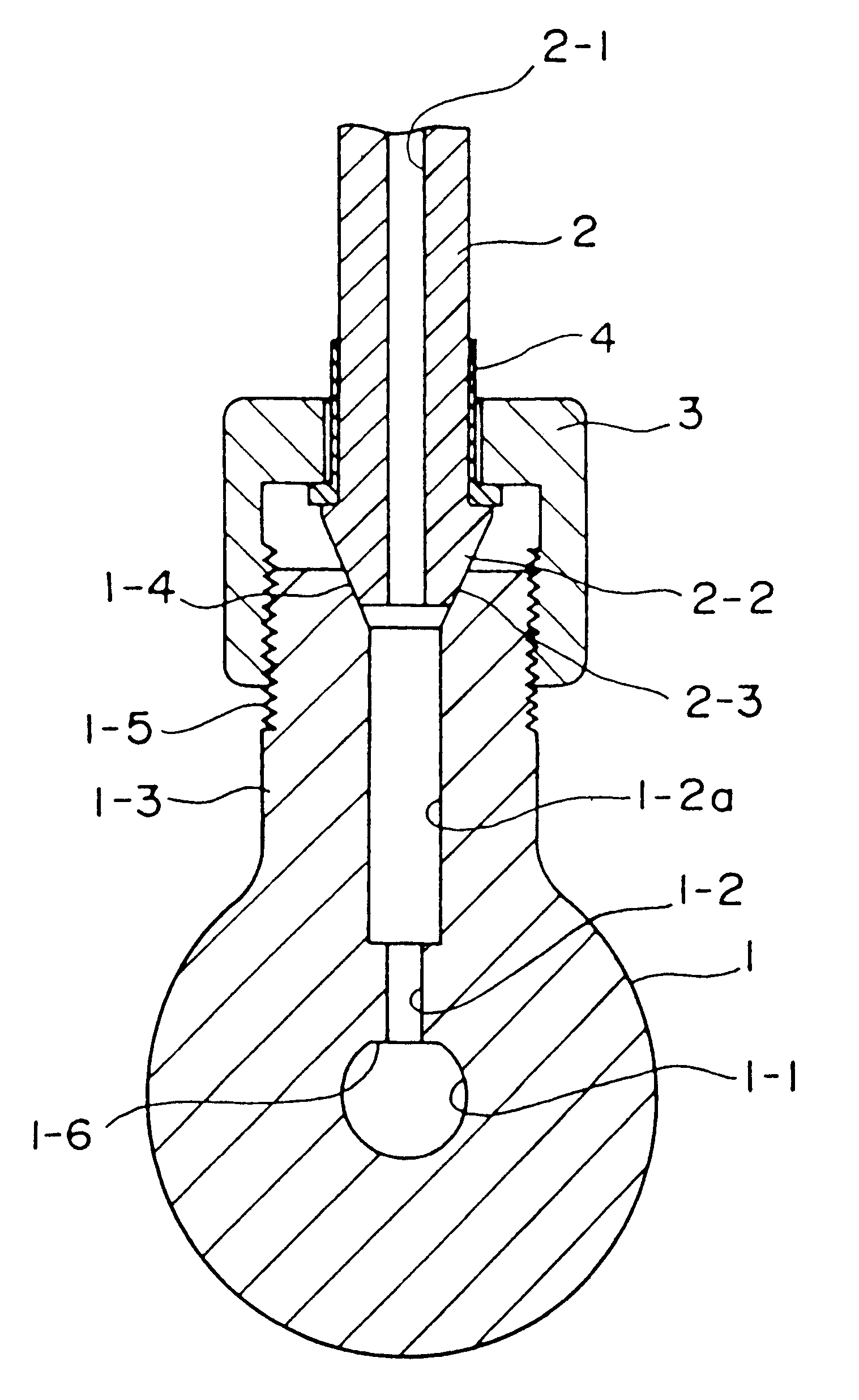
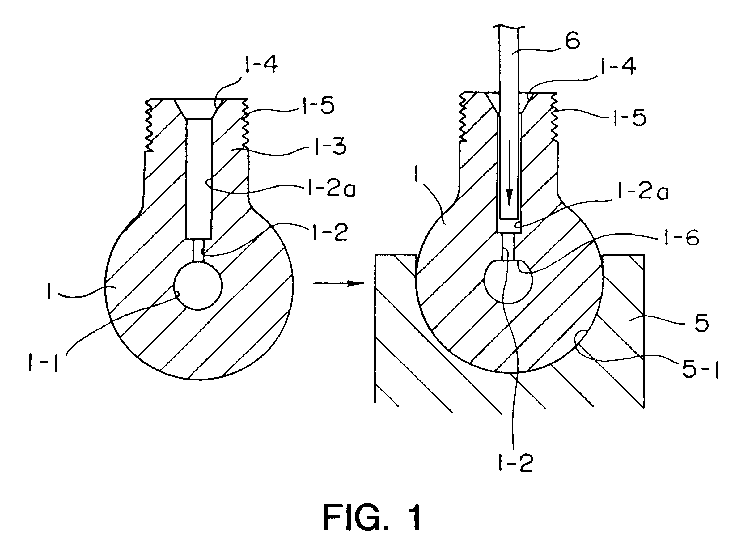
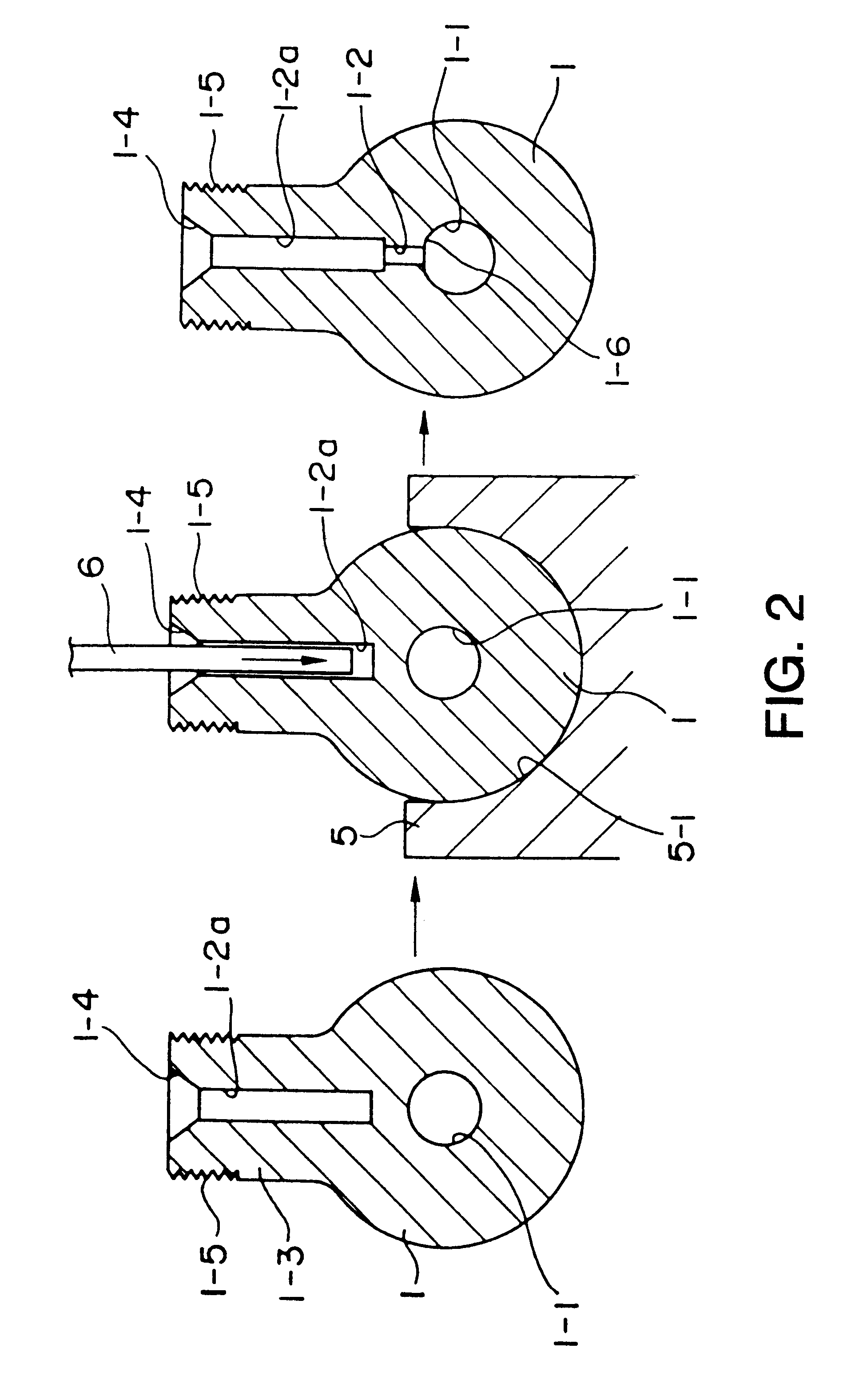
In FIG. 1 through FIG. 20, numeral 1 designates a main pipe rail, numeral 2 designates a branch pipe, numeral 3 designates a fastening box nut, numeral 3' designates a fastening nut (male nut), numeral 4 designates a sleeve washer, numeral 5 designates a lower die, numeral 6 designates a punch, numerals 7-1 and 7-2 designate diameter expanding pieces, numeral 8 designates a fixing jig, numeral 9 designates a pulling device, numeral 10 designates a pressing device, numeral 11 designates a punch, numeral 12 designates a steel ball receiver and numeral 12' designates a slug receiver.

Explaining firstly a common rail having boss portions of an outside screw (male screw) type in reference to FIG. 1 through FIG. 5, a main pipe rail 1 of a common rail is a forged product of a material S45C or the like having a comparatively thick wall tubular portion with, for example, a diameter of 28 mm and a wall thickness of 9 mm in which an inner portion along an axis center constitutes a flow path 1-1...


PUM

PropertyMeasurementUnit
Pressureaaaaaaaaaa
Flow rateaaaaaaaaaa
Residual stressaaaaaaaaaa

Abstract

A common rail is provided for promoting inner pressure fatigue strength at location in proximity to a branch pipe. The common rail includes a main pipe rail with a main flow path. At least one boss in provided on the peripheral wall and includes a branch hole communicating the main flow path. The branch pipe is provided with a connecting head that has a pressing face at and end of the branch pipe. The pressing face of the branch pipe is urged into a pressure receiving seat of the boss. A compressive residual stress is provided at location in the peripheral wall where the main flow path of the main pipe rail communicates with the branch hole. The compressive residual stress increases the pressure fatigue strength by substantially canceling tensile stress.

Description

1. Field of the InventionThe present invention relates to a common rail such as a high pressure fuel manifold in an accumulator fuel injection system of a diesel internal combustion engine, a block rail or the like.2. Description of the Prior ArtsConventionally, there have been known common rails of this kind, for example, as illustrated by FIGS. 21 and 22. The common rail shown by FIG. 21 is of a system constituted by perforating branch holes 21-2 each having a pressure receiving seat face 21-4 communicating with a flow path 21-1 of a main pipe rail 21 and opened outwardly at a plurality of boss portions 21-3 provided at intervals at a peripheral wall portion in the axial direction on the side of the main pipe rail 21 comprising a circular pipe, engageably bring pressing seat faces 22-3 constituted by connection head portions 22-2 on the side of branch pipes 22 into contact with the pressure receiving seat faces 21-4 on the side of the main pipe rail 21 and screwing fastening box n...

Claims


Application Information

Patent Timeline
IPC IPC(8): B21C37/29B21C37/15F02M55/02
CPCB21C37/29F02M55/025F16L41/00
Inventor ASADA, KIKUOUSUI, MASAYOSHIWATANABE, EIJITAKIKAWA, KAZUNORI
Owner USUI KOKUSAI SANGYO KAISHA LTD
Why Eureka
Try Eureka