Oral isolation device with evacuation chambers

a technology of oral isolation and evacuation chamber, which is applied in the field of oral isolation devices, can solve the problems of no application for use with the upper teeth or on the lower teeth other than the front teeth, and many unique surgical difficulties for dentists

Inactive Publication Date: 2001-04-10
PREMIER DENTAL PRODS +1
View PDF15 Cites 83 Cited by
  • Summary
  • Abstract
  • Description
  • Claims
  • Application Information

AI Technical Summary

Benefits of technology

It is an object of the present invention to provide an oral isolation device which optimally retracts th

Problems solved by technology

During oral procedures, the dentist encounters many unique surgical difficulties.
For instance, the oral cavity is a small space within which to work; it is bacteria laden and rich in blood supply; there is saliva, debris and applied fluid and aerosol buildup; and, finally, many patients have difficulty in keeping their tongues from entering the operative field.
While this device is suitable for working on the front lower teeth, it has no application for use with the upper teeth or on lower teeth other than the front teeth.
An additional shortcoming of this device is that it only provides for evacuation of fluid collecting near the lingual mucosa at the base of the tongue.
While these two devices offer certain advances, they are not without shortcomings.
Second, while the devices offer some tongue retraction capabilities, they do so by tongue depression.
Tongue depression can be quite uncomfortable for the patient and is only a marginally effective technique since a patient's tongue can slip from beneath the depressor.
Third, both devices only provide for evacuation of pooled saliva and fluid, with Dahl doing so only on the buccal side of the gums.
Thus, the devices do not significantly increase the size of the operating field.
This can lead to patient discomfort and movement of the device.
A further shortcoming of this device is the placement system may cause obstruction of the operative field.
A first shortcoming is that the device provides for tongue depression instead of retraction; the drawback of which is discussed above.
A second shortcoming is that the device fits around the front of a patient's mouth, thereby creating a potential obstruction to the operating field.
Another shortcoming of the

Method used


Image

  • Oral isolation device with evacuation chambers
  • Oral isolation device with evacuation chambers
  • Oral isolation device with evacuation chambers

Examples


Embodiment Construction

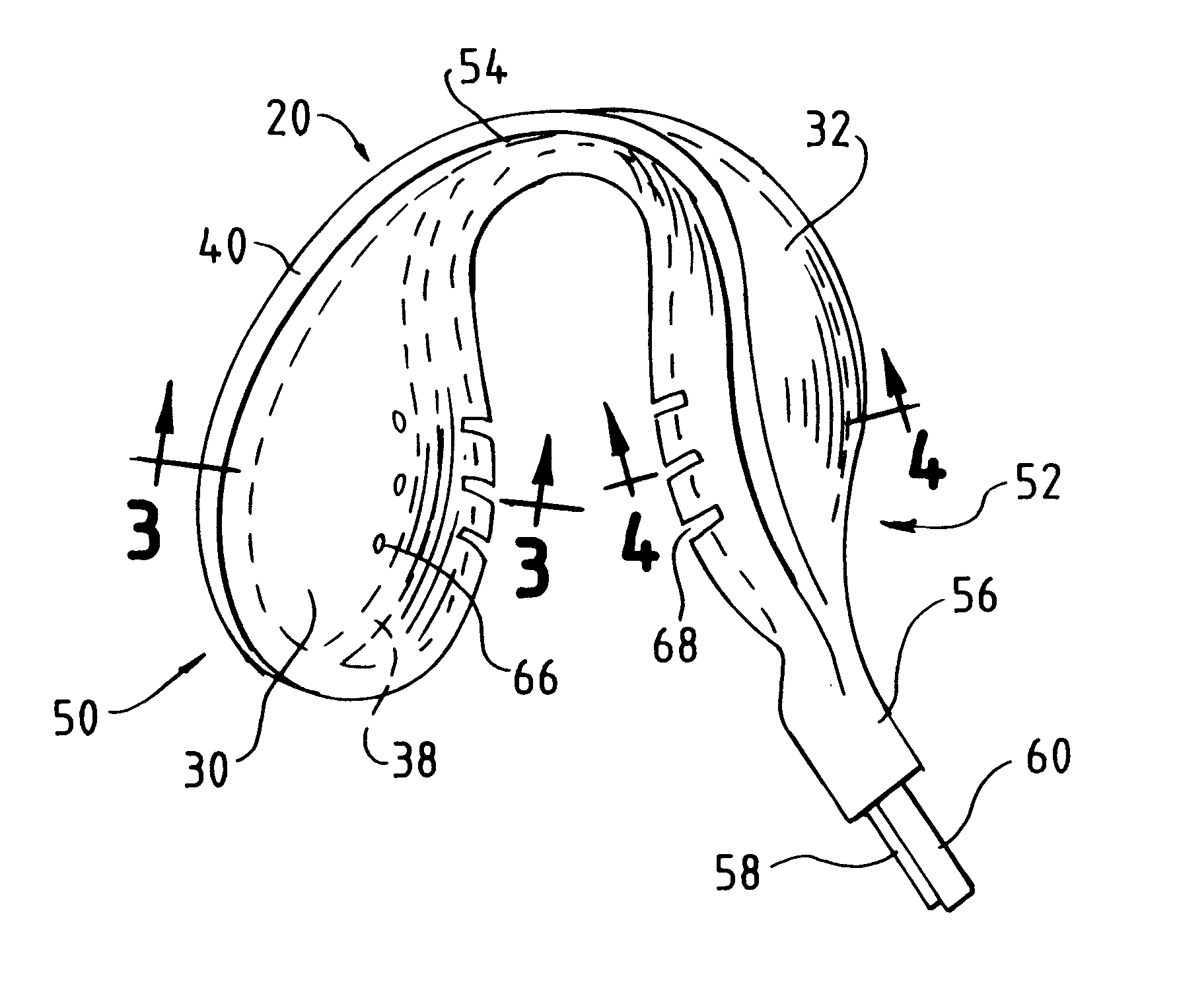
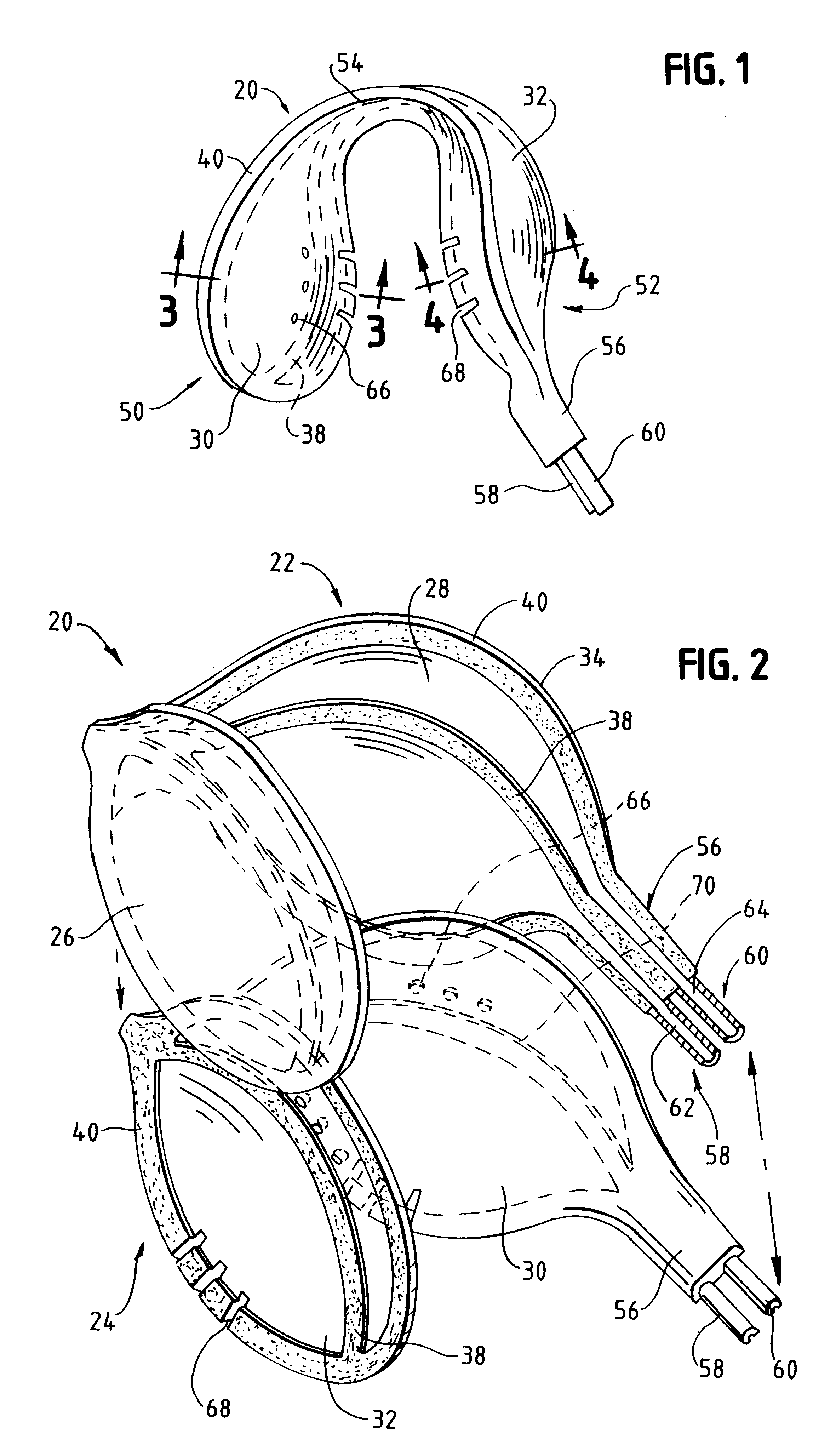
The following description of the preferred embodiment will be better understood with reference to the appended drawings. As those skilled in the art understand, the oral cavity is a difficult area within which to perform procedures. The dentist and patient are best served when the size of the operative field is optimized. The primary goal is to isolate the area in which a procedure is to be performed. A secondary goal is to keep that area as free as possible from collected saliva, fluid, aerosol, and debris. The present invention addresses those problems and concerns in an improved Oral Isolation Device (device) 20.

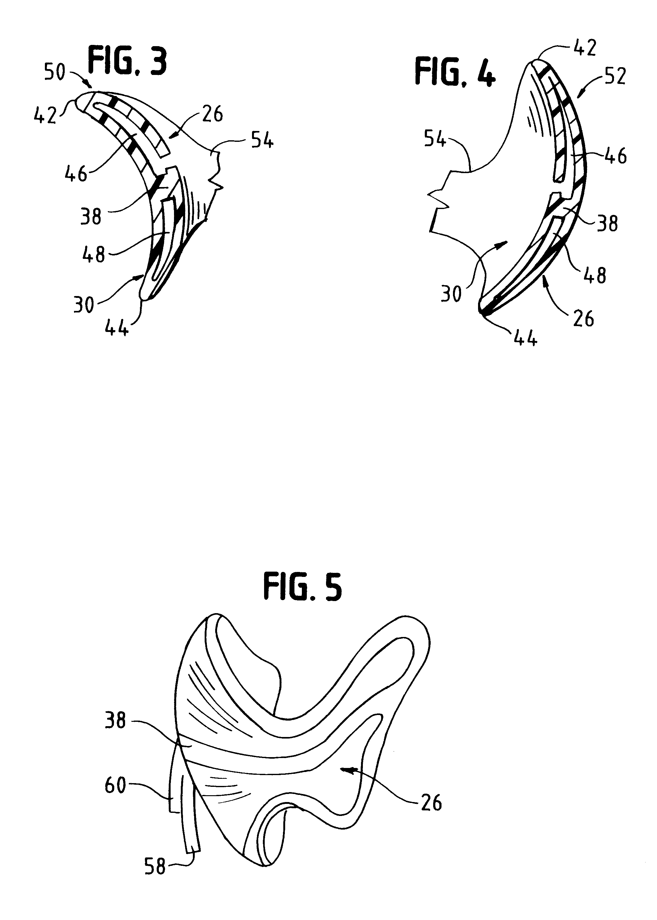
Turning to FIG. 1, a top view of device 20 is depicted. Turning to FIG. 2, it can be seen that in its preferred embodiment, device 20 is comprised of two sections, outer section 22 and inner section 24. While the preferred embodiment envisions an outer section and an inner section, this is done for manufacturing purposes only. The scope and spirit of the inventive device ...


PUM


Abstract

An essentially a U-shaped oral isolation device having a tongue arm, a buccal arm, and a hinge section is provided. The device is an essentially hollow member having an upper suction chamber and a lower suction chamber within the hollows of the oral isolation device. Each chamber further comprising suction inlet apertures through which saliva, fluid, aerosol mist, and debris can be evacuated from the operative site, and a suction outlet chamber through which the collected saliva, fluid, and debris are removed from the device. A U-shaped hinge member joins the buccal arm and the tongue arm. It has position memory which permits the user to squeeze the arm members toward one another for placement in the mouth and upon release, the arm members exert opposing positional influence against the tongue and cheek. Also provided is a method of use for the device in which the tongue arm and buccal arms are forced toward one another. The hinged member is then inserted into the patient's oral cavity and placed around the rearmost tooth. Upon proper placement of the device, the user releases the pressure on the arms of the device, the arms thereby exerting opposing positional influence against the cheek and tongue, resulting in retraction of the tongue and cheek, thereby creating a clear operative field. A reduced pressure high volume device is then attached to the upper chamber suction outlet and a low pressure reduced volume device is attached to the lower chamber outlet.

Description

I. TECHNICAL FIELDThe present invention relates to oral isolation devices for use in dental procedures and, more particularly, to an oral isolation device which optimizes the size of the operating field, provides unobstructed cheek and tongue retraction, and further includes fluid, aerosol, and debris evacuation chambers adapted to attach to suction devices, thereby keeping the operative field dry without causing tissue damage to surrounding tissue.II. BACKGROUND OF THE INVENTION AND PRIOR ARTDuring oral procedures, the dentist encounters many unique surgical difficulties. For instance, the oral cavity is a small space within which to work; it is bacteria laden and rich in blood supply; there is saliva, debris and applied fluid and aerosol buildup; and, finally, many patients have difficulty in keeping their tongues from entering the operative field.Over the years, many appliances have been devised to assist in maintaining a clear and clean operative field. One example is seen in U....

Claims


Application Information

Patent Timeline
IPC IPC(8): A61C5/00A61C5/14A61C17/06A61C17/08A61C17/10
CPCA61C17/043A61C5/14A61C5/90A61C17/08
Inventor COSTELLO, WILLIAM J.
Owner PREMIER DENTAL PRODS
Why Eureka
Try Eureka