Bladder control device actuator

a control device and actuator technology, applied in the field of bladder control device actuators, can solve the problems of users of these devices that cannot generate even a moment of sufficiently high bladder pressure to initiate flow through the aforementioned devices, and users that cannot generate pressur

Inactive Publication Date: 2001-04-10
FEELSURE HEALTH CORP
View PDF18 Cites 20 Cited by
  • Summary
  • Abstract
  • Description
  • Claims
  • Application Information

AI Technical Summary

Benefits of technology

Devices and methods according to the present invention give a large number of people, previously unable to use intraurethral devices, the ability to deal with urinary incontinence using such devices. In particular, the present invention allows users of a class of intraurethral devices to initiate urine flow through the devices without having to generate high bladder pressure. One class

Problems solved by technology

Many existing intraurethral devices seek to duplicate the function of normal urinary sphincter control.
There exists a class of potential users of these devices that cannot generate even a moment of sufficiently high bladder pressure to initiate flow through the afore

Method used


Image

  • Bladder control device actuator
  • Bladder control device actuator
  • Bladder control device actuator

Examples


Embodiment Construction

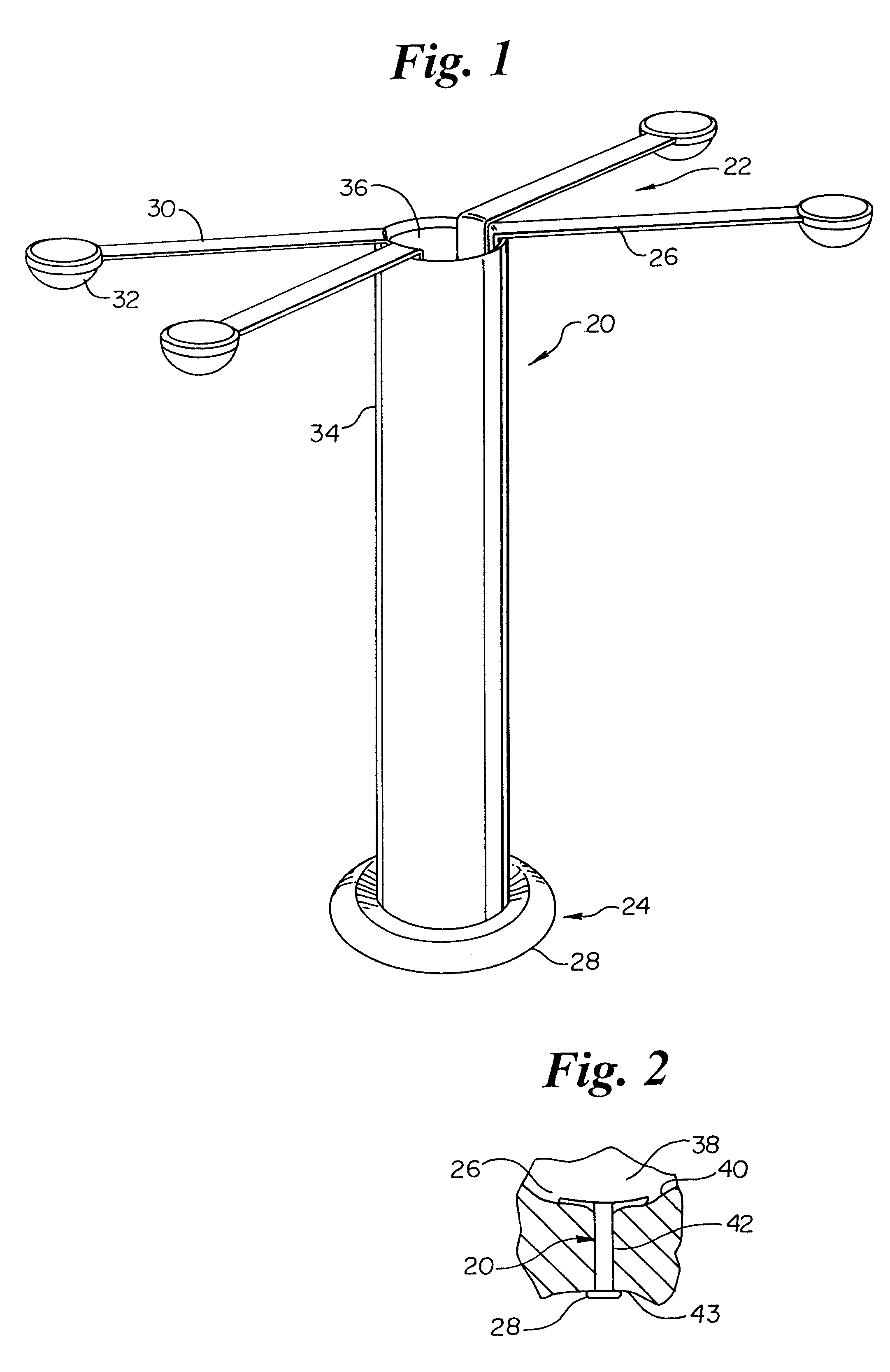
FIG. 1 is a perspective view of a bladder control device for insertion in a female urethra;

FIG. 2 is cutaway, fragmentary side view of the bladder control device of FIG. 1 disposed in a female urethra, between the bladder and urethral meatus;

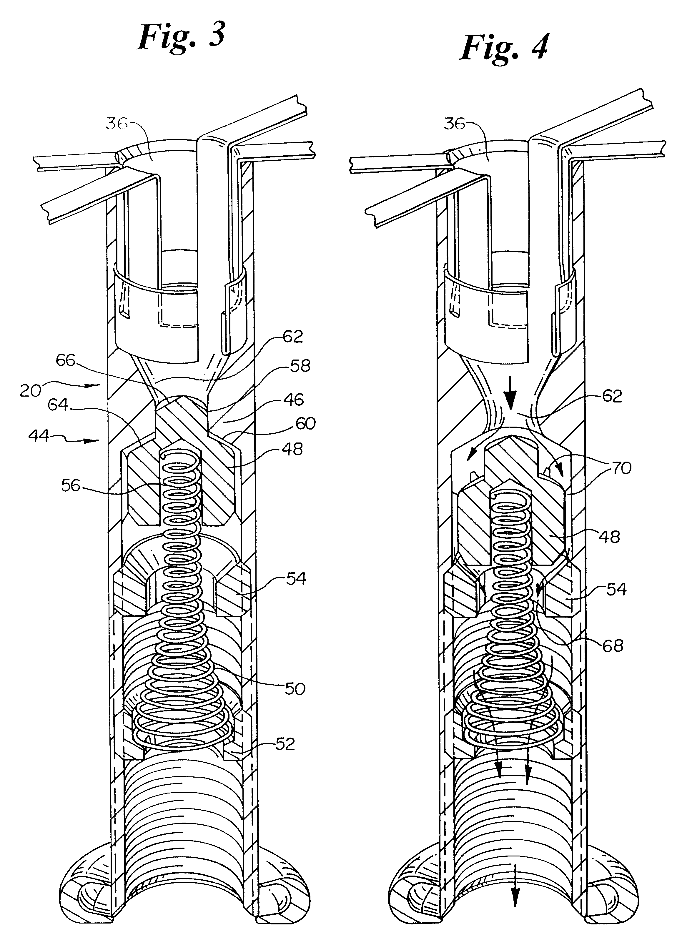
FIG. 3 is a cutaway, perspective view of the bladder control device of FIG. 1 having a urine flow lumen and a valve stopper in a proximal, closed position;

FIG. 4 is a cutaway, perspective view of the bladder control device of FIG. 3 having the valve stopper in a distal, open position;

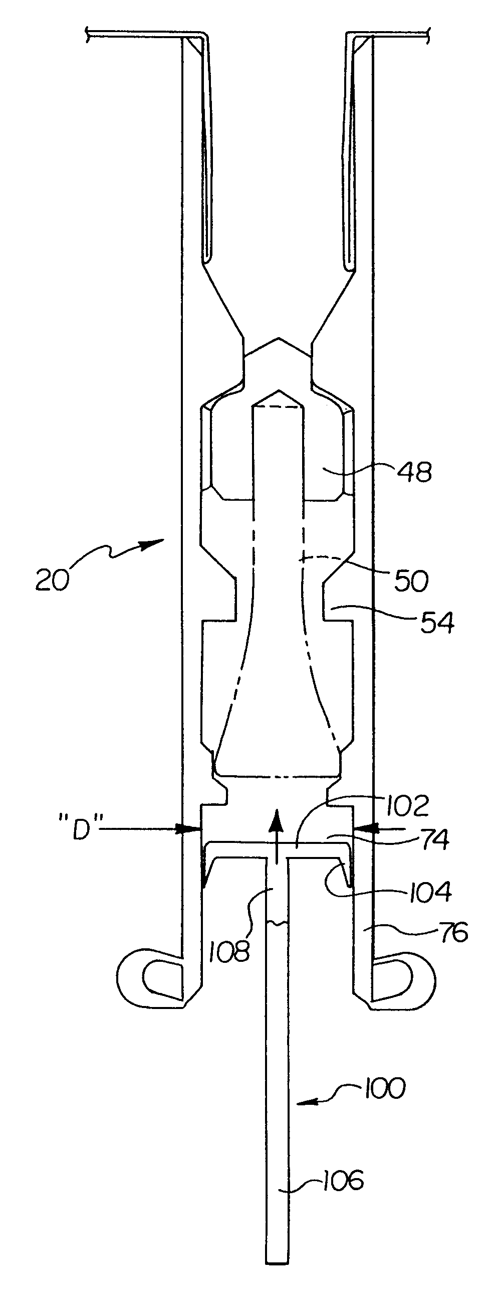
FIG. 5 is a cutaway, side view of the device of FIG. 1 in closed position, having a plunger actuator in the process of being positioned in the flow lumen;

FIG. 6 is a cutaway, side view of the device of FIG. 6 in open position, after the plunger has been withdrawn and urine flow initiated;

FIG. 7A is a cutaway, side view of a bladder control device in closed position having a housing wall including a lumen therein, and an elongate actuating member disposed within the ...


PUM


Abstract

A system for initiating urine flow in intraurethral bladder control devices having a housing, a flow lumen, a valve biased to close, a distal end disposed near the urethral meatus, and a proximal end disposed near the bladder. The system includes an actuator device to open the valve. One intraurethral bladder control device has a higher velocity flow region near the valve distal end, such that the Bernoulli effect generates a negative pressure on the valve, keeping the valve in an open position once urine flow commences. One valve includes a spring biased stopper in the urine flow lumen. One actuator device is a suction device adapted to mate to the intraurethral device distal end and capable of pulling the stopper into the open position. Suction devices include plungers, syringes, and squeezable bulbs. Another actuator device includes a magnet capable of moving a magnetically responsive stopper. Yet another actuator device includes an elongate member disposed within the device housing and operably coupled to the stopper. Grasping and manipulating a free distal end of the elongate member causes the stopper to open and initiate urine flow.

Description

The present invention relates generally to medical devices and more particularly to intraurethral bladder control devices. Specifically, the invention relates to devices adapted to initiate urine flow in intraurethral devices and, more specifically, capable of initiating urine flow in users unable to generate sufficient bladder pressure due to atonic bladder disorder.The use of sphincter and bladder control devices is wide spread in the field of the present invention. See, for example, commonly assigned U.S. Pat. Nos. 5,512,032; 5,701,916; 5,701,916; and 5,722,932, herein incorporated by reference. Many existing intraurethral devices seek to duplicate the function of normal urinary sphincter control. This usually involves opening a valve in response to a user initiated stimulus, for example, an initial moment of high bladder pressure generated by the user of the device. In some devices, once begun, flow can be maintained without requiring continuing high bladder pressure.There exist...

Claims


Application Information

Patent Timeline
IPC IPC(8): A61F2/00
CPCA61F2/0009A61F2/0018
Inventor NISHIOKA, CRAIGSHEN, CHI-HONG
Owner FEELSURE HEALTH CORP
Why Eureka
Try Eureka