Structure of a ratchet wrench

Inactive Publication Date: 2001-04-24
CHEN YU TANG
View PDF5 Cites 56 Cited by
  • Summary
  • Abstract
  • Description
  • Claims
  • Application Information

AI Technical Summary

Problems solved by technology

However, this type of wrench 10 has the drawback as that of FIG. 1 and the wrench 10 is often dislocated from the nut 12.
Besides, the process of tightening and loosening of nut 12 by using this wrench 10 is slow.
However, this design has other drawbac

Method used


Image

  • Structure of a ratchet wrench
  • Structure of a ratchet wrench
  • Structure of a ratchet wrench

Examples


Embodiment Construction

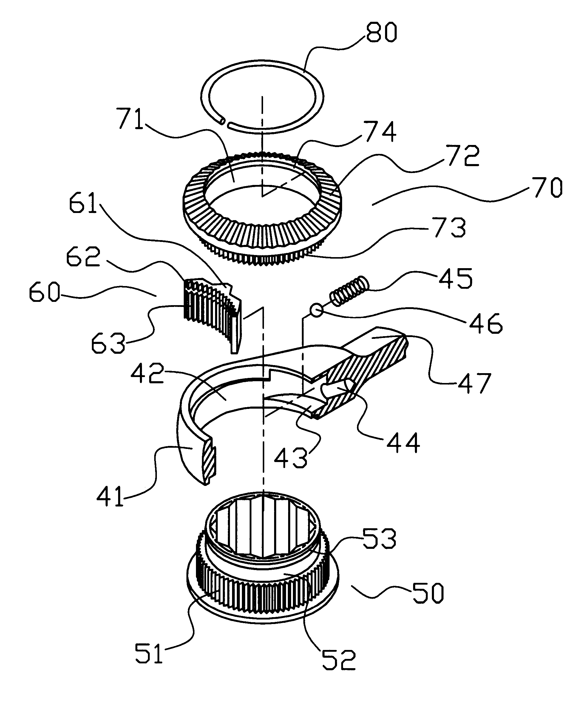
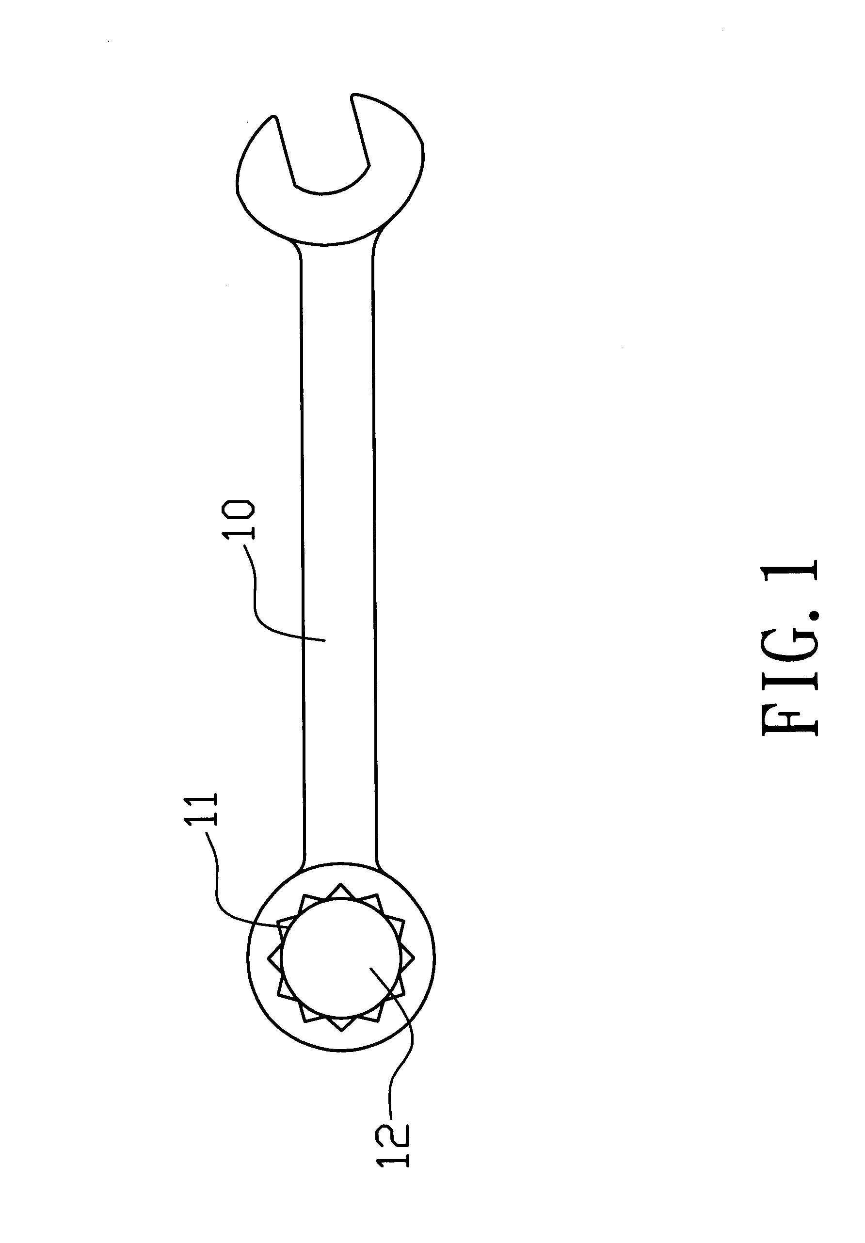
Referring to FIGS. 6 and 7, there is shown a wrench head 41 having a circular opening 42 to contain a ratchet wheel 50. A rotating disc 70 is used to cover the opening 42. A cavity 43 is provided to the circular opening 42, adjacent to the rod body of the wrench of the present invention to contain a restrictive teeth structure 60. The bottom end of the cavity 43 is provided with a ball hole 44 to contain a spring 45 and a steel ball 46, and the steel ball 46 urges against a protruded block 61 of the restrictive teeth structure 60.

The top end of the ratchet teeth 51 of the ratchet wheel 50 is extended to an extension 52 having a relative small diameter, and the extension 52 is provided with a circular groove 53 for the mounting of a fastening ring 80.

The restrictive teeth structure 60 includes a top ratchet teeth 62 and a bottom ratchet teeth 63, the ratchet teeth 51 of the ratchet wheel 50 corresponds to the bottom ratchet teeth 63 to produce interlinked tightening or free rotation ...


PUM


Abstract

The present invention relates to the structure of a ratchet wrench, and in particular, to a ratchet wrench which can provides high torque engagement in application, wherein a ratchet wheel is inserted into a circular opening on the wrench head of a common ratchet wrench, and a cavity is provided to the circular opening adjacent to one side of the rod body of the wrench for mounting a restrictive teeth structure, the end terminal of the cavity is provided with a ball hole to contain a spring and a steel ball, and the restrictive teeth structure is urged by the steel ball, thereby the high torque movement of the ratchet wheel is controlled.

Description

a) Technical Field of the InventionThe present invention relates to a wrench structure, and in particular, to a ratchet wrench capable of providing high torque movement.b) Description of the Prior ArtAs shown in FIG. 1, a common conventional wrench 10 has a plurality of engaging notches 11 formed as one unit with the wrench 10 and the notches 11 moves together with the wrench 10 to rotate a nut 12. When the wrench 10 is rotated to a certain degree, as a result of restriction by object around the wrench 10, the wrench 10 has to be lifted up and placed at the original position and then repeat the process in order to rotate the nut 12. As a result of repeating engagement and disengagement of the wrench 10 with the nut 12, the notch 11 of the wench 10 is often dislocated in the process of tightening or loosening of the nut 12.FIG. 2 is another prior art wrench 10 having a bent structure to provide convenient holding of the handle of the wrench 10 by a user. However, this type of wrench ...

Claims


Application Information

Patent Timeline
IPC IPC(8): B25B13/00B25B13/46
CPCB25B13/463
Inventor CHEN, YU-TANG
Owner CHEN YU TANG
Why Eureka
Try Eureka