Inductor built-in electronic parts using via holes

Inactive Publication Date: 2001-04-24
MURATA MFG CO LTD
View PDF15 Cites 108 Cited by
  • Summary
  • Abstract
  • Description
  • Claims
  • Application Information

AI Technical Summary

Problems solved by technology

However, the prior art LC filter has had a problem in that when the width of the pattern electrode is thickened, a value of inductance generated by the pattern electrode made within an equal area becomes small and a large floating capacity is generated between the electrodes similar to the capacitor electrodes which vertically face each other.
The result is a drop in Q, contrary to the purpose of the design modification.
It is noted that this kind of problem also exists in other built-in inductor electronic parts such as prior art inductors and LC resonators in which a pattern electrode acts as an inductor element and is formed by means of thick film printing.
The prior art LC filter 1 shown in FIG. 8 also has had a problem that although the Q of the whole is improved when the space between the pattern electrode and the vertically disposed capacitor electrode is widened, a thickness of the whole, i.e. the size thereof, is increased and it cannot be mounted within small equipment su

Method used


Image

  • Inductor built-in electronic parts using via holes
  • Inductor built-in electronic parts using via holes
  • Inductor built-in electronic parts using via holes

Examples


second embodiment

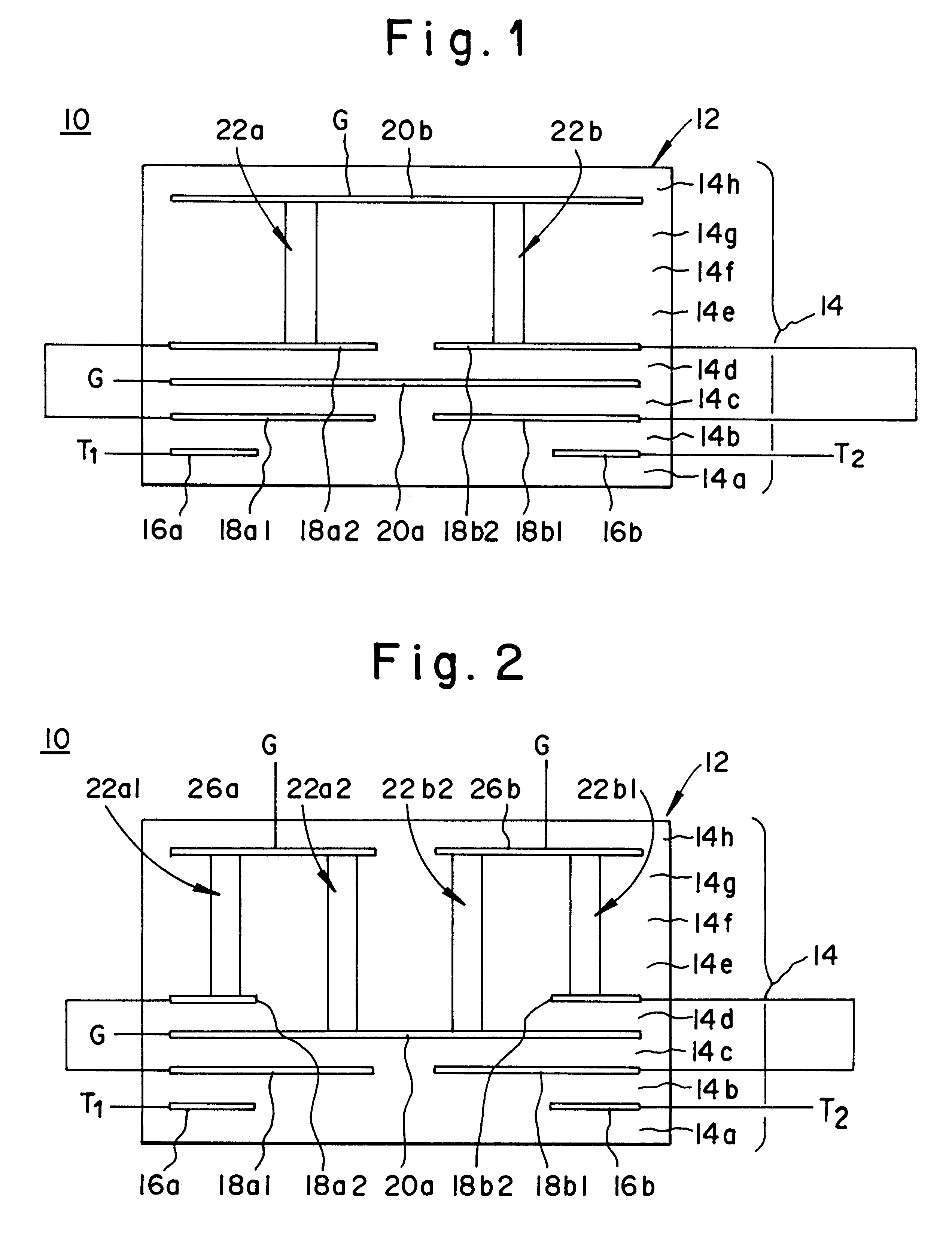
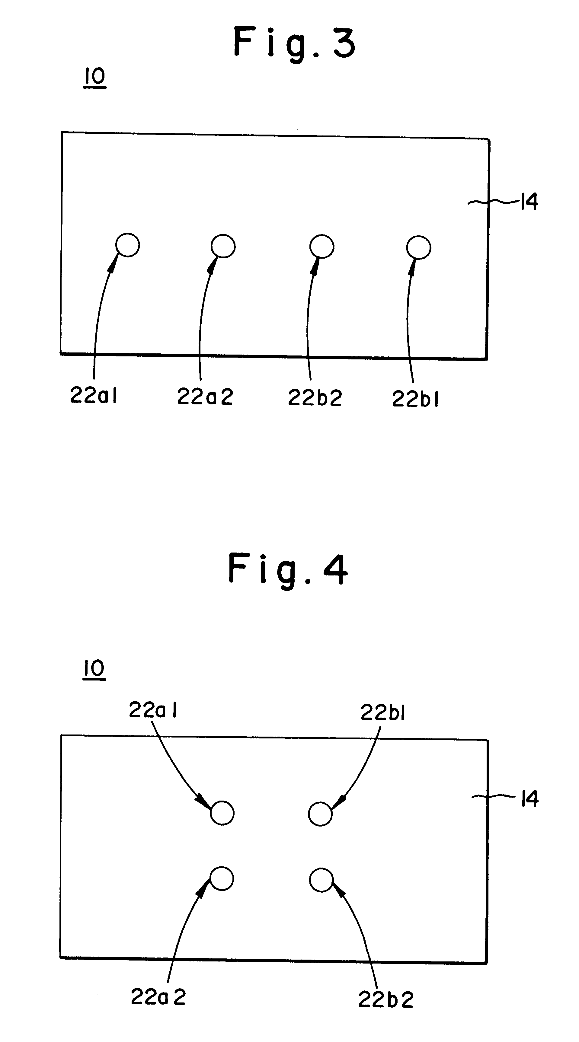
FIG. 2 is a diagrammatic view showing the present invention and FIG. 3 is a diagrammatic view showing a main part thereof. As compared to the embodiment of the present invention shown in FIG. 1, the embodiment of the present invention shown in FIGS. 2 and 3 is characterized in that each inductor element is formed by two via holes.

That is, as compared to the embodiment shown in FIG. 1, third and fourth small common electrodes 18a2 and 18b2 are formed between the fourth and the fifth dielectric layers 14d and 14e and first and second connecting electrodes 26a and 26b are formed between the uppermost dielectric layers 14g and 14h leaving a space therebetween in the embodiment shown in FIGS. 2 and 3. It is noted that a part of each of these connecting electrodes 26a and 26b needs not be extended to the end of the dielectric layers 14 and each end needs not be exposed out of the side face of the laminate 12. First and second columnar via holes 22a1 and 22b1 which penetrate through the pl...

third embodiment

FIG. 5 is a diagrammatic view showing the present invention. An LC filter 10 shown in FIG. 5 also includes rectangular parallelepiped multi-layered substrates or laminate 12 formed by laminating a number of dielectric layers 14a, 14b, 14c, . . . or the like made out of a number of ceramic layers.

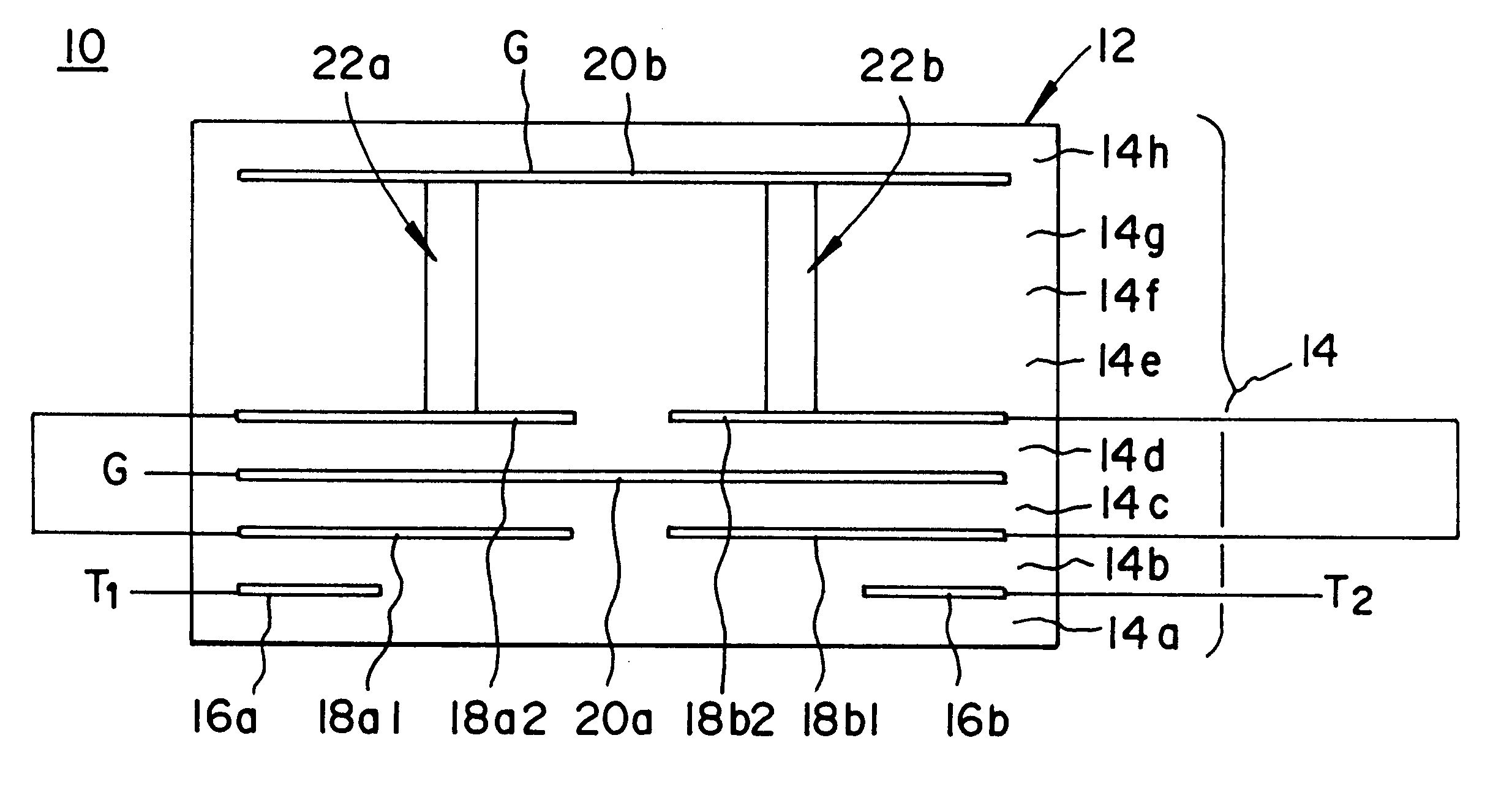
First and second common electrodes 18a1 and 18b1 are formed between the bottom dielectric layers 14a and 14b leaving a space therebetween.

First and second capacitor electrodes 16a and 16b are formed between the second and third dielectric layers 14b and 14c from the bottom leaving a space therebetween. These first and second capacitor electrodes 16a and 16b face to the first and second common electrodes 18a1 and 18b1, respectively, via the second dielectric layer 14b.

Third and fourth common electrodes 18a2 and 18b2 are formed between the third and fourth dielectric layers 14c and 14d from the bottom leaving a space therebetween. The third and fourth common electrodes 18a2 and 18b2 face to th...


PUM


Abstract

A small inductor built-in electronic part whose Q is high is provided. An LC resonator comprises a laminate composed of a number of laminated electronic layers. Capacitor electrodes, common electrodes, and ground electrodes are formed between the dielectric layers. Two via holes are formed penetrating through the plurality of intermediate dielectric layers in the thickness direction thereof leaving a space therebetween. These via holes act as inductor elements.

Description

1. Field of the InventionThe present invention relates to electronic parts with an integrally built-in inductor and, more particularly, to electronic parts such as an inductor, an LC resonator, band-pass filter and an LC filter for use in a portable radio equipment, for example.2. Description of Related ArtFIG. 7 is an equivalent circuit diagram showing one example of an LC filter acting as a band-pass filter to which the present invention can be applied. The LC filter includes two LC resonators R1 and R2. One LC resonator R1 comprises a first inductor L1 and a first capacitor C1 connected in parallel, and the other LC resonator R2 comprises a second inductor L2 and a second capacitor C2 connected in parallel. It is noted that the first and second inductors L1 and L2 are electromagnetically coupled to each other. One end of the first LC resonator R1 is connected to a first input / output terminal T1 via a third capacitor C3 and one end of the second LC resonator R2 is connected to a s...

Claims


Application Information

Patent Timeline
IPC IPC(8): H01G4/40H03H1/00H03H7/01H01F27/00H01F17/00H03H5/02H03H7/09
CPCH01G4/40H03H1/00H03H7/0115H03H7/1775H03H2001/0085
Inventor KATO, NOBORUTOJYO, ATSUSHI
Owner MURATA MFG CO LTD
Why Eureka
Try Eureka