Piston-cylinder unit

Inactive Publication Date: 2001-05-01
ZF FRIEDRICHSHAFEN AG
View PDF5 Cites 14 Cited by
  • Summary
  • Abstract
  • Description
  • Claims
  • Application Information

AI Technical Summary

Problems solved by technology

The disadvantage with these embodiments is that, when these piston/cylinder units are used in spring s

Method used


Image

  • Piston-cylinder unit
  • Piston-cylinder unit
  • Piston-cylinder unit

Examples


Example

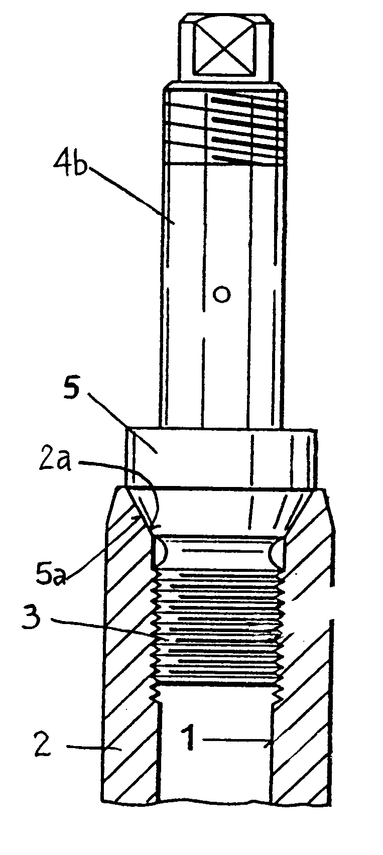
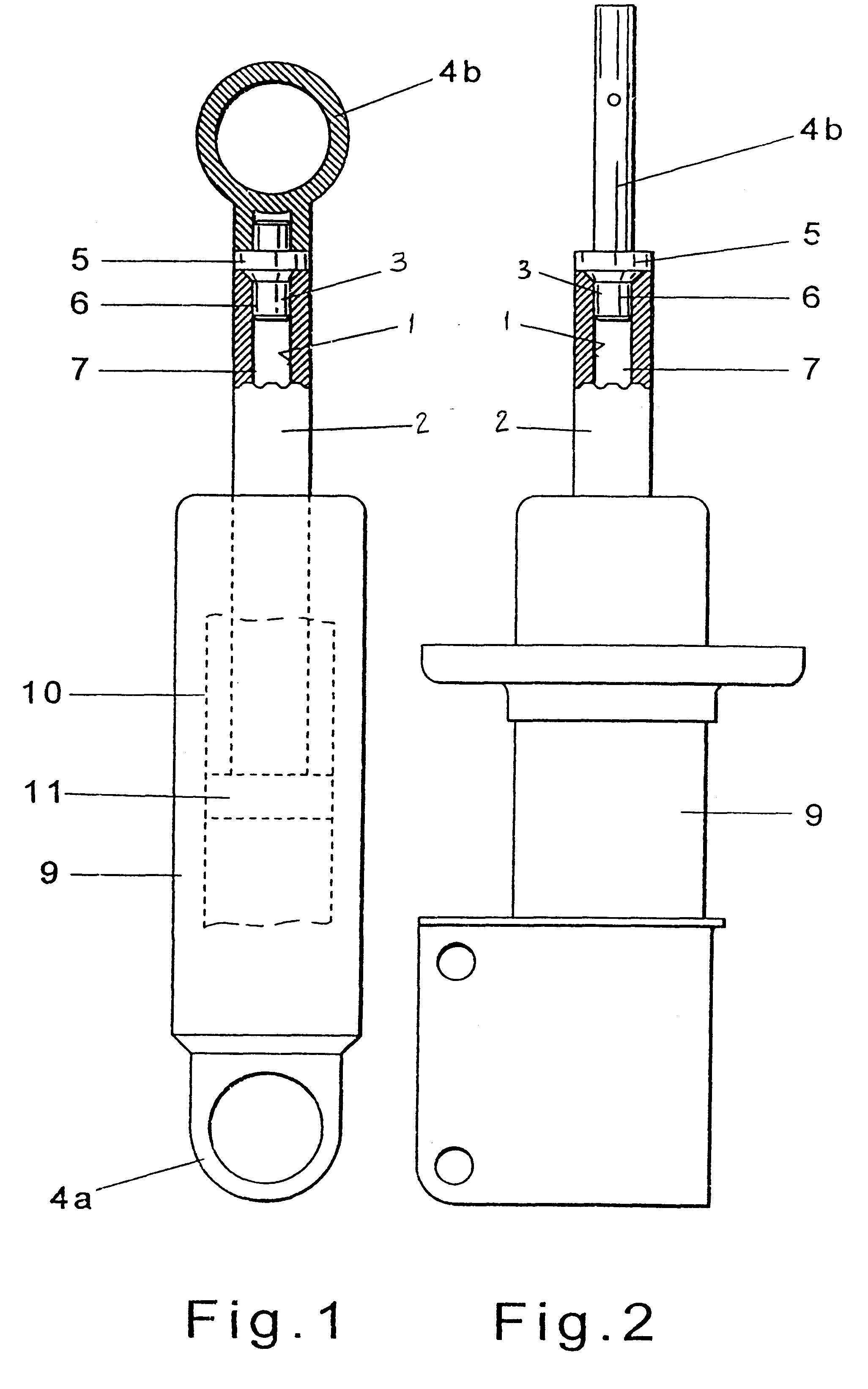
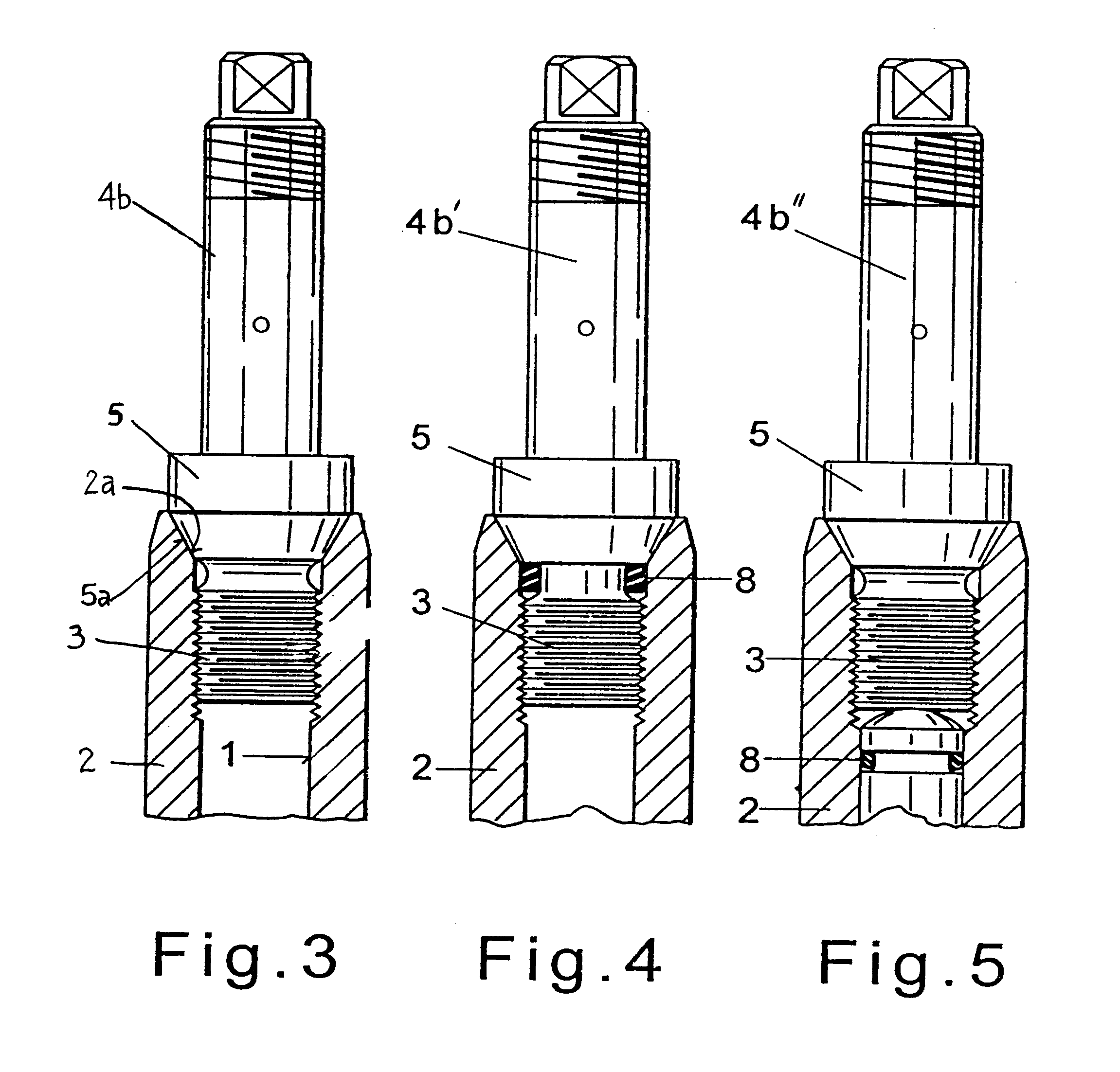
A piston / cylinder unit 100 according to an embodiment of the present invention is illustrated in FIG. 1 as a shock absorber comprising an outer tube 9 with a working cylinder 10 arranged therein. A piston 11 fastened to a piston rod 2 is arranged in the working cylinder 10 with the piston rod 2 so that the piston 11 is axially movable. A fastening element 4a is connected directly to the outer tube 9 and a fastening element 4b is connected to the piston rod 2 via a bolt 6 with a thread 3. The fastening element 4b also includes a collar 5 with a tapered surface which tapers from an outer diameter toward the thread 3 of the bolt 6. The piston rod 2 is of a hollow design and has a bore 1 in a cavity 7. The bore has a tapered widening surface into which the tapered surface of the collar 5 engages.

FIG. 2 shows another embodiment of the piston / cylinder unit 101 according to the present invention as a spring strut. In this embodiment, the piston / cylinder unit is likewise provided with an ou...


PUM


Abstract

A piston/cylinder unit includes a working cylinder, a piston attached to a piston rod and arranged so that it is axially movable in the working cylinder, and a fastening element threaded into a threaded bore of the piston rod. The bore in the piston rod includes a tapered surface which widens outward starting from the diameter of the thread and the fastening element has a corresponding diminishing tapered surface arranged on a collar which diminishes from the outside to the diameter of the thread.

Description

1. Field of the InventionThe invention relates to a piston / cylinder unit comprising a working cylinder, a piston attached to a piston rod and arranged in the working cylinder so that it is axially displaceable in the working cylinder, and a fastening element screwed into a threaded bore of the piston rod.2. Description of the Related ArtPrior art piston / cylinder units, e.g. self-pumping hydropneumatic spring struts with internal leveling, are disclosed, for example, in German reference DE 33 16 069A1 in which a tubular piston rod is closed at its outer end by a screw-in bolt. The screw-in bolt has an offset which is pressed onto the end of the piston rod by the torque applied to the threaded joint. This type of piston-rod closure offers the advantage of allowing different screw-in bolts to be threaded into the piston rod so that the same piston rod can be used with many different screw-in bolts. This threaded joint is designed principally for transmitting forces in the axial directi...

Claims


Application Information

Patent Timeline
IPC IPC(8): F16F9/32F16F9/54
CPCF16F9/3221F16F9/54B60G2204/128B60G2206/41
Inventor BECK, HUBERTMOLITOR, MATTHIAS
Owner ZF FRIEDRICHSHAFEN AG
Why Eureka
Try Eureka