Folded helix antenna design

a helical antenna and antenna design technology, applied in the field of antennas, can solve the problems of limited changes in the height of conventional quadrifilar helix antennas, affecting other components of the system, and affecting the impedance and performance of the antenna,

Inactive Publication Date: 2001-05-08
SIRIUS XM RADIO INC
View PDF10 Cites 45 Cited by
  • Summary
  • Abstract
  • Description
  • Claims
  • Application Information

AI Technical Summary

Problems solved by technology

Unfortunately, as is well known in the art, the height of a quadrifilar helix antenna is directly related to its impedance.
Consequently, any change in the height of the antenna will affect its impedance and its performance.
Hence, changes in height of conventional quadrifilar helix antennas typically require a redesign of the impedance matching circuit associated t...

Method used


Image

  • Folded helix antenna design
  • Folded helix antenna design
  • Folded helix antenna design

Examples


Embodiment Construction

While the present invention is described herein with reference to illustrative embodiments for particular applications, it should be understood that the invention is not limited thereto. Those having ordinary skill in the art and access to the teachings provided herein will recognize additional modifications, applications, and embodiments within the scope thereof and additional fields in which the present invention would be of significant utility.

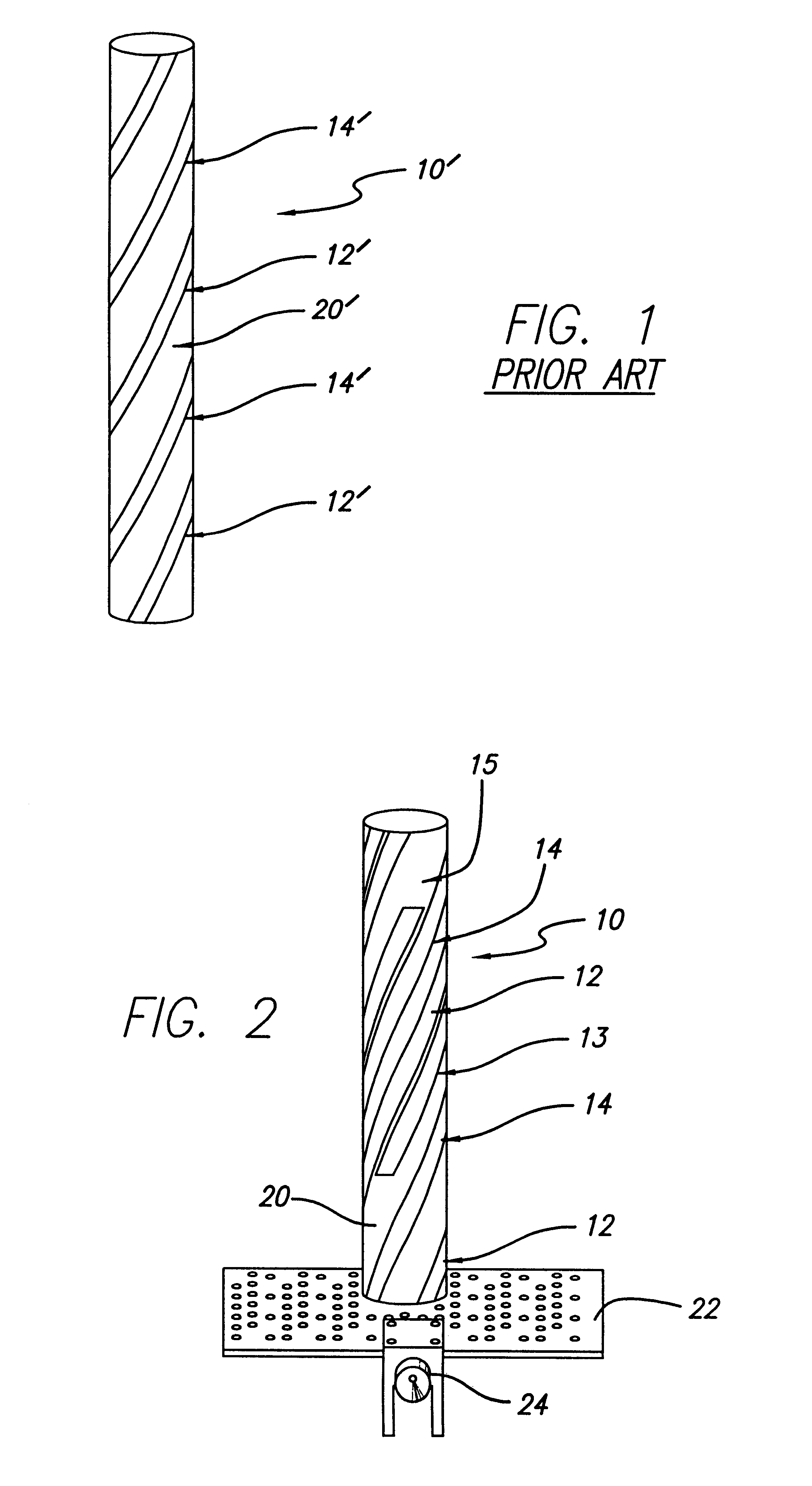
FIG. 1 is a front elevation a view of a typical conventional implementation of a quadrifilar helix antenna in accordance with the teachings of the prior art. As shown in FIG. 1, the antenna 10' includes four radiating elements of which two are shown 12' and 14' mounted on a plastic dielectric tube substrate 20'. The remaining two radiating elements are obscured by the tube. The dielectric tube 20' may be constructed of Ultem or other suitable low loss material e.g., Lexan or urethane.

In the design of a conventional quadrifilar helix antenna...


PUM


Abstract

A folded helical antenna. Generally, the inventive antenna includes plural radiating elements of conductive material. In the preferred embodiment, the antenna is a quadrifilar helix antenna having four radiating elements. Each radiating element is constrained into a helical shape. In accordance with the present teachings, each radiating element extends in a first direction and has a portion thereof folded in a second direction, the second direction being substantially parallel to the first direction. The novel method of making a quadrifilar helix antenna of the invention includes the steps of: ascertaining desired antenna characteristics for a given application; ascertaining limitations on antenna height for the application; fabricating a helical antenna in accordance with the desired antenna characteristics; and adjusting the height of the antenna in accordance with the limitations by folding the radiating elements thereof.

Description

BACKGROUND OF THE INVENTION1. Field of InventionThis invention relates to antennas. Specifically, the present invention relates to helical antennas.2. Description of the Related ArtHelical antennas are well known in the art. See for example U.S. Pat. No. 5,541,617 issued Jul. 30, 1996, to Connolly et al.; U.S. Pat. No. 5,349,365 issued Sep. 20, 1994 to Ow et al.; U.S. Pat. No. 5,134,422 issued Jul. 28, 1992 to Auriol; U.S. Pat. No. 4,349,824 issued Sep. 14, 1982 to Harris; U.S. Pat. No. 5,255,005 issued Oct. 19, 1993 to Terret et al.; U.S. Pat. No. 5,170,176 issued Dec. 8, 1992 to Yasunaga et al.; and U.S. Pat. No. 5,198,831 issued Mar. 30, 1993 to Burrell et al., the teachings of which are hereby incorporated herein by reference. See also "A Shape-Beam Antenna For Satellite Data Communication" published Oct. 12, 1976, by Randolph W. Bricker, Jr. AP-S Session 4, 1630, at the AP-S. International Symposium held in 1976 in Amherst, Mass., U.S.A., pp. 121-126.As noted by Auriol, helical...

Claims


Application Information

Patent Timeline
IPC IPC(8): H01Q11/08H01Q1/36H01Q11/00H01Q1/38
CPCH01Q1/36H01Q1/38H01Q11/08
Inventor LICUL, STANISLAVCHATZIPETROS, ARGYRIOS A.
Owner SIRIUS XM RADIO INC
Why Eureka
Try Eureka