Conveyor-belt roller assembly

a conveyor belt and roller technology, applied in the direction of shafts, bearing components, ball bearings, etc., can solve the problems of inability to meet the above parameters, the load-bearing component of the conveyor belt has very few strengthening characteristics, and the stoppage of the conveyor belt is extremely costly, so as to increase the roller support strength and facilitate the installation. the effect of quick and secur

Inactive Publication Date: 2001-05-22
LUFF INDS
View PDF16 Cites 36 Cited by
  • Summary
  • Abstract
  • Description
  • Claims
  • Application Information

AI Technical Summary

Benefits of technology

In accordance with the current invention, the above-identified problems are overcome by the addition of an anti-lock shield element which protects the polycap and additional rotating parts from the outside environment by providing a non-rotating, strong, heat resistant external outer surface for the roller assembly that is essentially flush with the cylindrical roller. Also, present in a preferred embodiment is a new rubber dust shield, which essentially seals the polycap and labyrinth seal from dust and particles if they penetrate the anti-lock shield. The novel polycap design, preferably constructed of 30% glass filled polypropylene, has two internal annular rings bridged with offset ribs for increased roller support strength. The inner labyrinth seal is tapered, and preferably constructed from 30% glass filled polypropylene, allowing it to be press-fit into the polycap and making installation more quick and secure.
The present invention is directed...

Problems solved by technology

Although the requirements for a conveyor-belt roller assembly are known, producing an assembly that complies with all of the above parameters has yet to be accomplished.
However, the load-bearing component of the assembly comprises very few strengthening characteristics and is too easily broken under heavy load.
The stoppage of rotation is extremely costly in that there is potential for damage to be caused to the cylindrical roller and roller assembly as well as to the belt itself.
Shutting down the conveyor-belt to replace broken roller assemblies can result in a huge financial penalty, therefore protection of the roller assembly and the rotating parts is extremely important.
However, the base of the assembly, which in this particular instance represents the load-bearing portion of the assembly, has little or no strengthening characteristics and can support only a limited load.
In addition, the exterior rotating end of the assembly is open to the outside environment, and nothing prevents the external environment from coming into contact with and disrupting...

Method used


Image

  • Conveyor-belt roller assembly
  • Conveyor-belt roller assembly
  • Conveyor-belt roller assembly

Examples


Embodiment Construction

The present invention will be described below in detail with the aid of the accompanying drawings, in which:

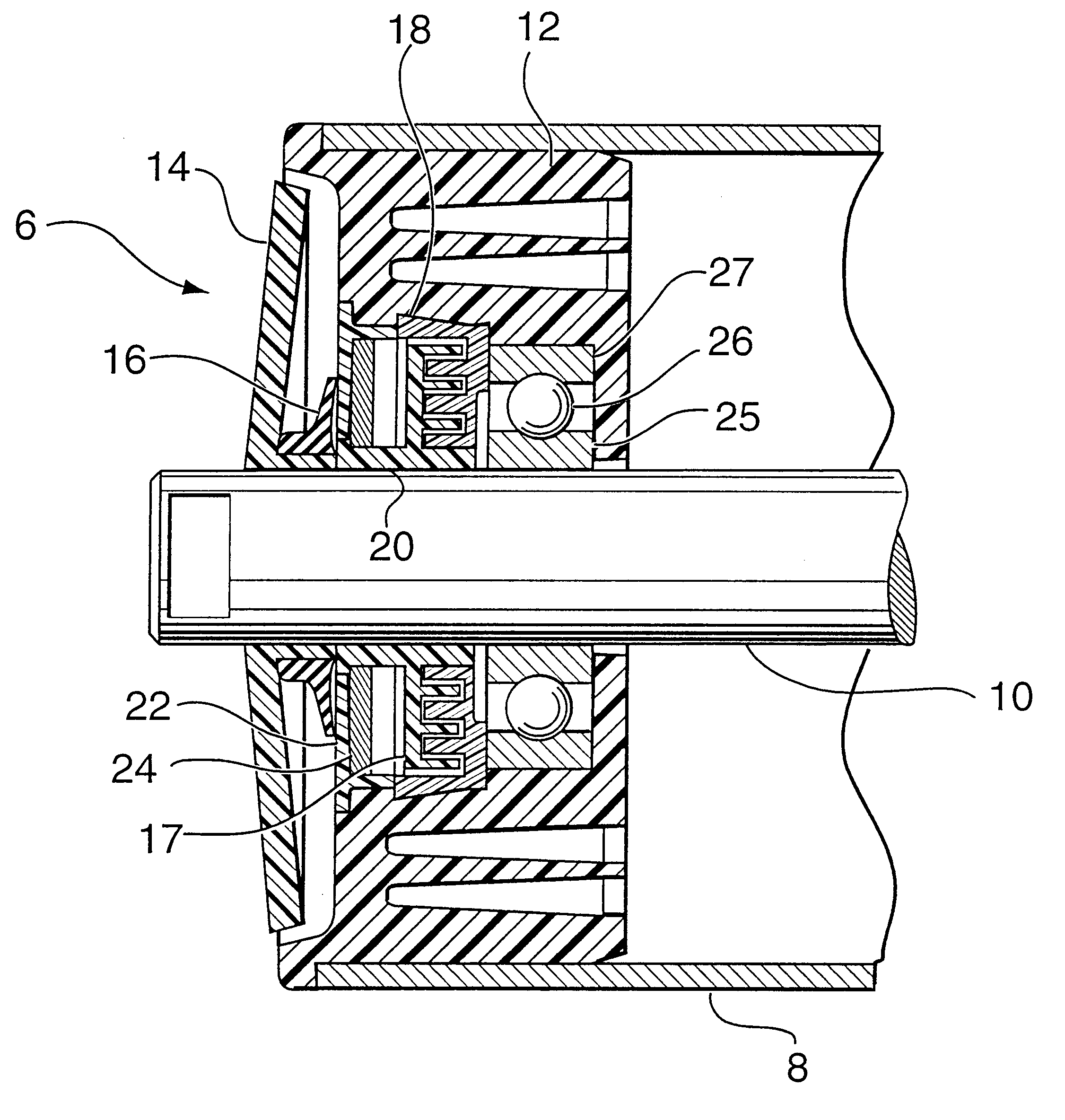
FIG. 1 is a cross-sectional view of a mounted conveyor-belt roller assembly constructed from the preferred materials;

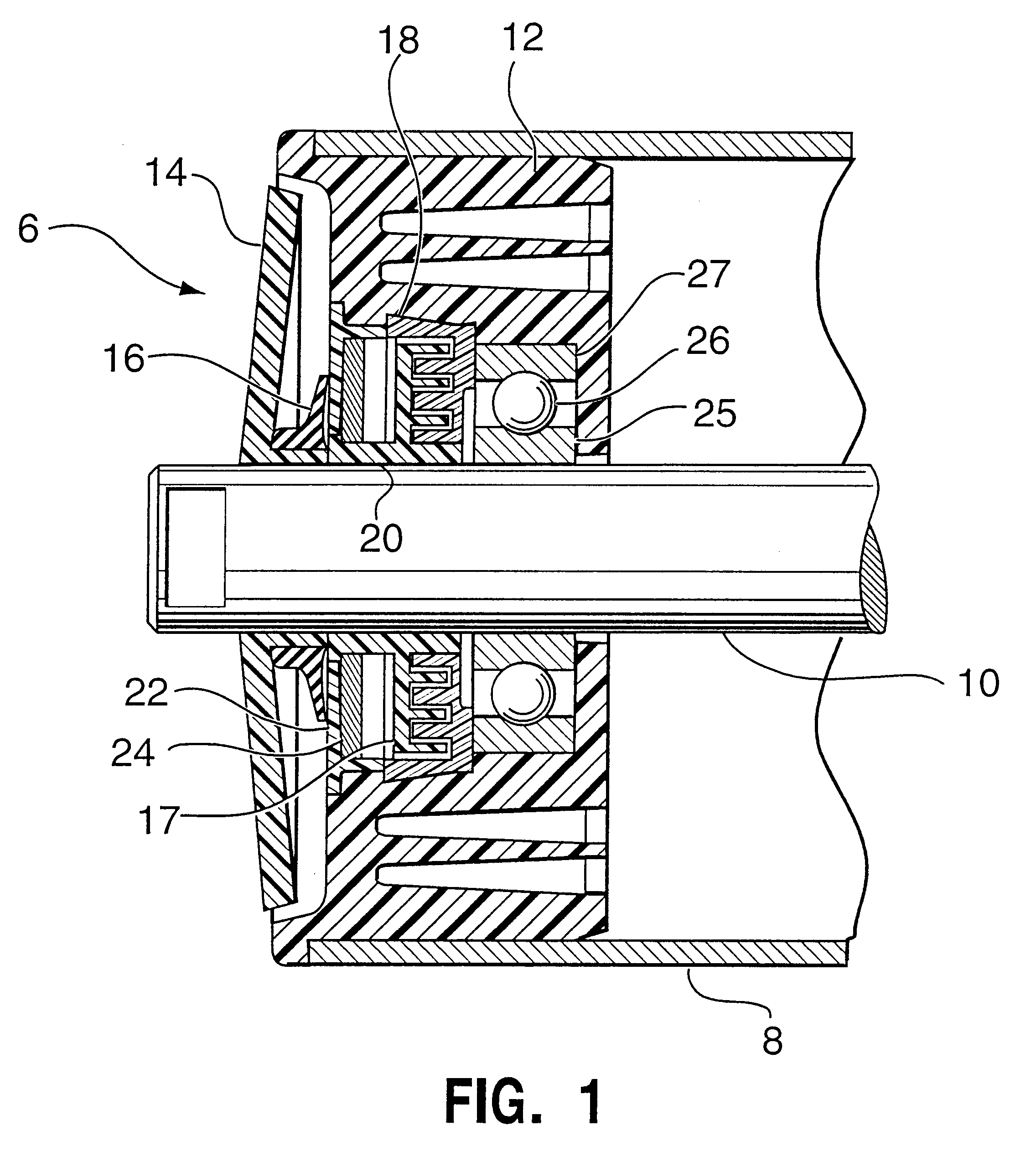
FIG. 2 is a diagrammatic view of the external surface of an anti-lock shield;

FIG. 2A is a cross-sectional view taken through 2A--2A of FIG. 2 of an anti-lock shield constructed from the preferred material;

FIG. 3 is an end elevational view of the posterior side of a polycap;

FIG. 3A is a cross-sectional view taken through 3A--3A of FIG. 3 of a polycap constructed from the preferred material;

FIG. 3B is an enlarged fragmented cross-sectional view of a bridging rib positioned across an annular ring of a polycap taken through 3B--3B of FIG. 3 constructed from the preferred material;

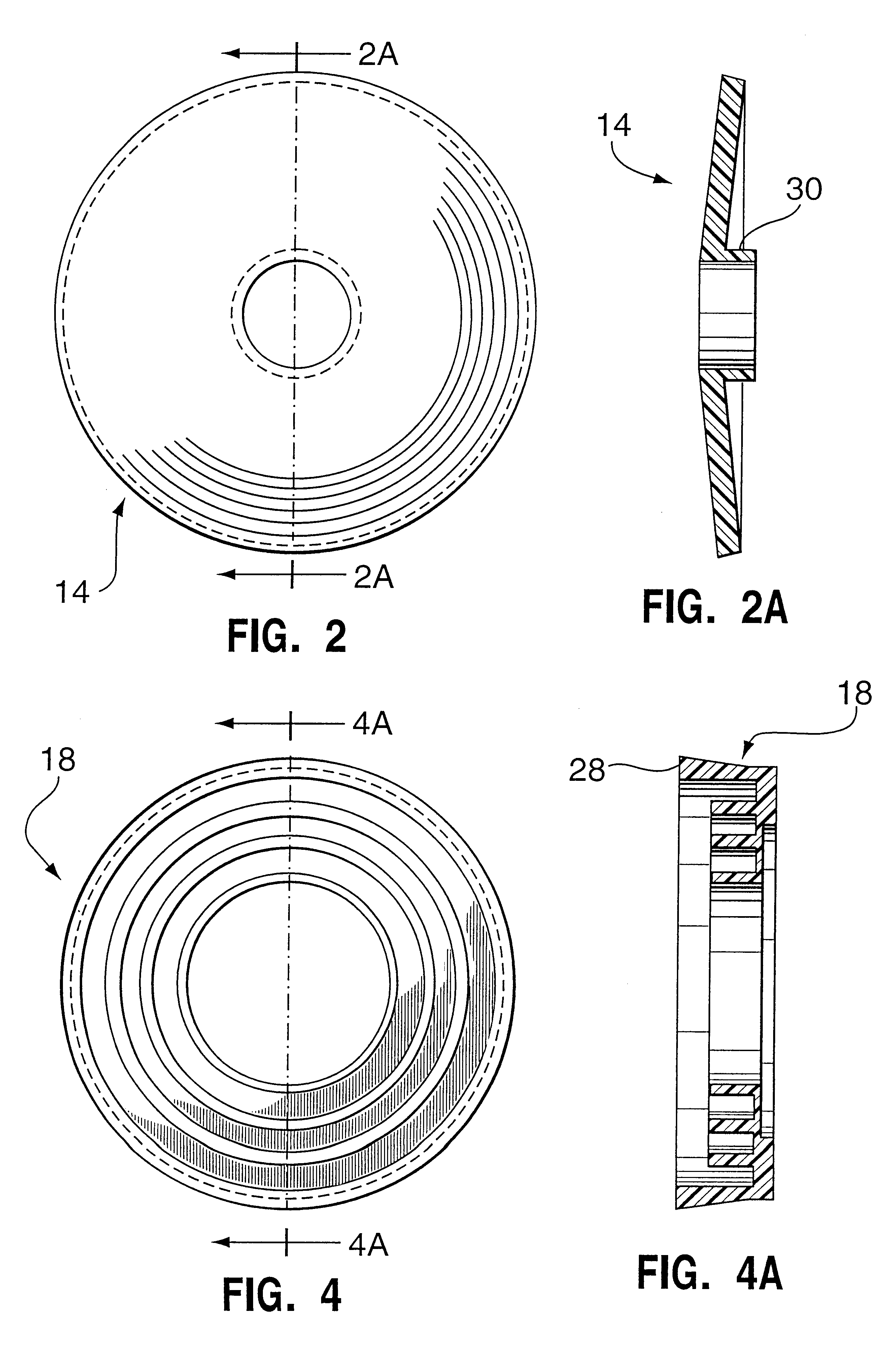
FIG. 4 is an end elevational view of a tapered inner labyrinth seal; and

FIG. 4A is a cross-sectional view of a tapered inner labyrinth seal taken through 4A--4A of FIG. 4 constructed from t...


PUM


Abstract

A conveyor-belt roller assembly secured inside a conveyor-belt roller and onto an inner shaft, preferably used in conveyor-belts used for carrying high loads of material in hazardous environments. The conveyor-belt roller assembly has a stationary anti-lock shield which protects the rotating exterior surface from coming into contact with the outside elements for example debris and machinery. A dust shield is also position aft of the anti-lock shield to prevent the penetration of small particles and dust into the inner workings of the conveyor-belt roller assembly. The conveyor-belt roller assembly also has deep rings in the load-bearing portion for thermal expansion and contraction as well as heat dissipation. Bridging ribs are positioned across the deep rings to greatly increase the strength and therefore load-baring capacity of the conveyor-belt roller assembly. A tapered labyrinth seal is used so that it can be press locked into position making installation quicker and easier. The main load-baring component and tapered labyrinth seal component are preferably fabricated from a high strength, heat resistant 30% glass filled polypropylene.

Description

The present invention is related to a roller for use with a conveyor-belt, particularly conveyor-belts for handling heavy loads in potentially dangerous environments.A conveyor-belt roller assembly is a roller like device, which fits inside either end of a cylindrical roller tube of a conveyor-belt, and carries the cylindrical roller tube while being mounting on and rotating around an inner shaft, thus allowing rotation of the cylindrical roller tube. It is well known that conveyor-belt roller assemblies must withstand incredible pressure from the great loads that they carry. Other characteristics of the roller assemblies are that they must withstand severe bombardment from the elements, function within a potentially hazardous environment and remain as reliable and maintenance free as possible so as to be safe when used and to be financially beneficial. Although the requirements for a conveyor-belt roller assembly are known, producing an assembly that complies with all of the above ...

Claims


Application Information

Patent Timeline
IPC IPC(8): B65G39/09B65G39/00
CPCB65G39/09F16C13/022F16C33/80F16C19/06F16C2326/58
Inventor FASOLI, LUIGI G.
Owner LUFF INDS
Why Eureka
Try Eureka