
Device and method for profiling grinding worms

a technology of profiling and worms, applied in the direction of worms, gear teeth, turning apparatus, etc., can solve the problems of limited flexibility or a high setting-up cost, disadvantage of being very slow, and partly still exist disadvantages, etc., to achieve short dressing time, low pre-setting construction effort, and high flexibility

Inactive Publication Date: 2001-05-22
REISHAUER
View PDF6 Cites 42 Cited by
  • Summary
  • Abstract
  • Description
  • Claims
  • Application Information

AI Technical Summary

Benefits of technology

The aim of the present invention is to specify a method and a device by means of which, despite the little presetting constructional effort required and despite high flexibility, the profiling of the entire active grinding worm thread profile is possible with short dressing times. According to the invention, this is achieved by the combination of a dressing profile disc, coated with hard material grains on two faces, for profiling the two grinding worm thread flanks and a radius-forming roll, arranged coaxially hereto and coated on the circumference with hard material grains, for profiling the tip of the grinding worm thread, the active zone of the radius-forming roll being geometrically configured and arranged in such a way that it can be brought into use without collision by axial displacement and pivoting of the dressing spindle relative to the grinding worm. Instead of the double tapered dressing disc coated with hard material grains on two sides, the combination of two single tapered dressing discs, for example, may also be used.
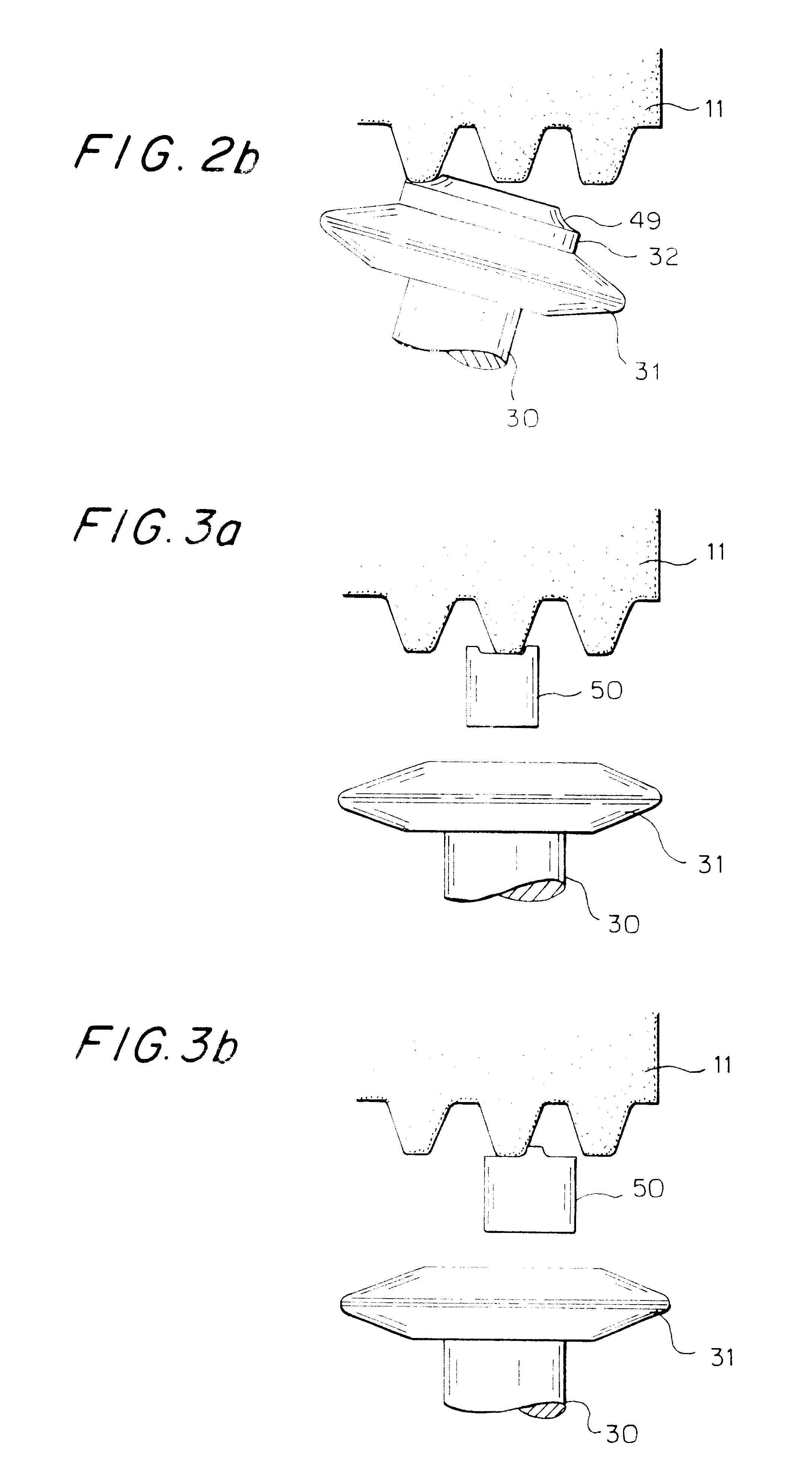
A variant of the invention is the dressing of the grinding worm thread tip by means of a hard material radius-forming tool, mounted on the pivoting support of the dressing spindle, instead of the above radius-forming roll, as a result of which the displacement travel of the dressing device between the dressing of the thread and the circumference of the grinding worm can be reduced.

Problems solved by technology

However, the advantage of the high efficiency of this dressing method is offset by the disadvantage of limited flexibility or a high setting-up cost.
However, it has the disadvantage of being very slow.
This disadvantage partly still exists even if, as in DE-A 196 24 842 A1, the line-by-line profiling is combined with the use of dressing profile discs.

Method used


Image

  • Device and method for profiling grinding worms
  • Device and method for profiling grinding worms
  • Device and method for profiling grinding worms

Examples


Embodiment Construction

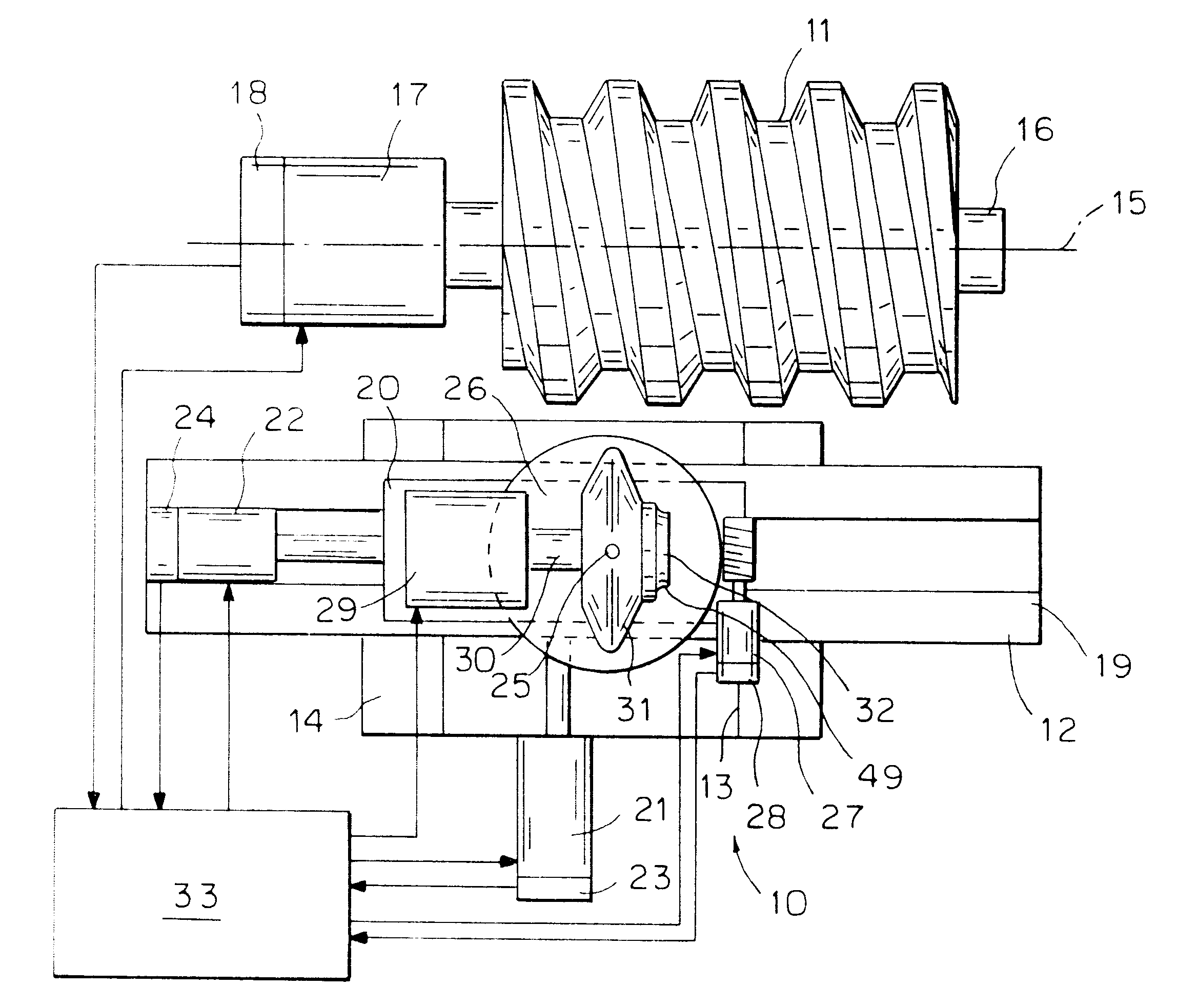
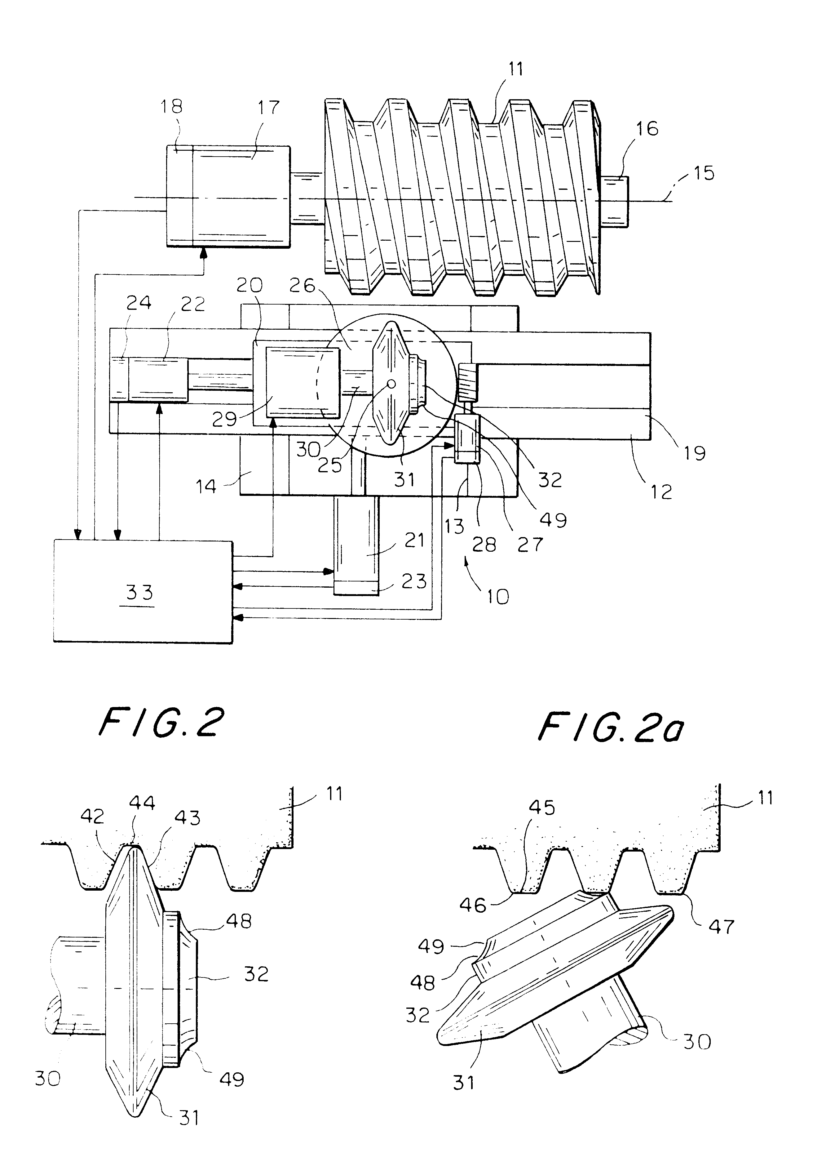
FIG. 1 shows a dressing device 10 for profiling a grinding worm 11. The dressing device may be designed, for example, according to DE-A-197 06 867.7. It comprises a cross slide, a first slide 12 being displaceable along a guide 13 of a machine base 14 perpendicularly to the axis 15 of the grinding spindle 16. The grinding worm 11 is mounted on the spindle 16, which is driven by a motor 17 and is connected to a rotary encoder 18. On the slide 12, a second slide 20 is displaceable guided in a guide 19 parallel to the axis 15. The slides 12, 20 are each displaceable by a respective motor 21, 22 with displacement feedback 23, 24. Mounted on the slide 20 is a rotary table 26, which is pivotable about an axis 25 perpendicular to the axis 15 and to the guide 13. The pivoting movement of the rotary table 26 is controlled by means of a further servomotor 27 with rotary encoder 28. Mounted on the rotary table 26 is a dressing motor 29, which drives the dressing spindle 30, on which the dressi...


PUM

PropertyMeasurementUnit
Flexibilityaaaaaaaaaa
Radiusaaaaaaaaaa
Circumferenceaaaaaaaaaa

Abstract

A radius-forming dressing roll (32) having a frustoconical working region (48) and an adjoining concave-toroidal working region (49) is mounted on the dressing spindle (30) coaxially to a dressing disc (31). In a first step, the flanks (42, 43) of the grinding-worm thread are profiled with the disc (31). After the dressing spindle (30) has been pivoted, the two tip radii (46, 47) and the cylindrical outer circumference (45) are profiled with the dressing roll (32). With little resetting effort and high flexibility, the method permits profiling with short dressing times.

Description

Prior ArtOne of the well-known and most widespread types of hard finishing of gears is the generation grinding of the tooth flanks by means of a cylindrical grinding wheel profiled in a worm shape at its circumference, the so-called grinding worm. The gear, when being ground, is brought into meshing engagement with the grinding worm, the tooth flanks of the gear being ground by the grinding-worm thread flanks and the tooth root being ground by the tip part of the grinding worm thread. This means that, before the grinding of the gear, the grinding worm thread has to be completely profiled in accordance with the tooth-gap profile of the workpiece.A whole series of methods is known for the profiling of the grinding worm thread, the most efficient and the most widespread being that in which one dressing profile disc each is used for the dressing of the left-hand flank and the right-hand flank and a forming roll is used for the dressing of the tip of the grinding worm thread. The three t...

Claims


Application Information

Patent Timeline
IPC IPC(8): B23F23/00B23F23/12B24B53/06B24B53/14B24B53/085B24B53/075B24B53/12B23F13/02B24B3/34
CPCB23F23/1225B24B53/075B24B53/085B24B53/14
Inventor SCACCHI, GIORGIO
Owner REISHAUER
Learn More