Double-side dresser

a dressing table and double-side technology, applied in the direction of gear teeth, gear teeth, gear-teeth manufacturing apparatus, etc., can solve the problems of requiring a fairly long time, tool is not flexible enough to adapt to the processing work, gear grinding wheel damage, etc., and achieve the effect of short dressing tim

Active Publication Date: 2015-01-08
LIEBHERR VERZAHNTECHNIK GMBH
View PDF6 Cites 16 Cited by
  • Summary
  • Abstract
  • Description
  • Claims
  • Application Information

AI Technical Summary

Benefits of technology

[0030]In the correction of a grinding tool, frequently only small areas such as tip reliefs, root reliefs, changes to the root rounding portion or of the profile angle are modified with respect to the standard profile. In this embodiment, a shape dresser can be combined with a profile dresser. With this tool combination, the total profile of the tool can then first be dressed using the profile dresser in an optimized process time and subsequently small profile areas such as the tooth root or the tooth crest can then still be modified line-wise using the shape dresser with the shape dressing process. A very flexible dressing with a short dressing time can be realized by this combination.

Problems solved by technology

The dressing process is thereby very flexible with respect to modifications, but requires a fairly long time since always only small regions of the tool are dressed simultaneously.
This tool is, however, not flexibly adaptable to the processing work due to the galvanic coating as would be the case with a dressable tool.
The spacing of the two tools has to be set exactly to the gear teeth if both dressing tools are in engagement since otherwise the gear grinding wheel is damaged.
A dresser of two different gear teeth is not possible with this arrangement.
The disadvantage of this embodiment is that two different gear tooth arrangements can only be dressed with limitations using this tool.
The gear tooth geometry of the gear tooth arrangement on a component can differ in this connection with respect to the module, crest / base rounding portions, profile spheres, number of teeth and other factors, which has the result that the two different gear tooth arrangements cannot be processed with one and the same worm gear wheel or grinding wheel.
The fact is disadvantageous for all embodiments for dressing wheels shown above that always only the tool for processing a gear can be dressed.
However, the time needed for the dressing cycle is disadvantageous in this respect since always only a part area of the grinding tool can be processed simultaneously.
The outer diameter of these dressing tools typically only differs in a minimal manner, however.
If such dressing wheels are to be used, this cannot take place using a dressing apparatus in accordance with the prior art, having two mutually oppositely disposed dressing tools, since otherwise a collision of the worm grinding wheel with the respective dressing tool just not being used would occur on the dressing of the worm grinding wheels.
An arrangement of the dressing tools such as described in the Fässler DSA dresser is not suitable for this application.
If the dressing wheels differ only minimally in diameter, collisions between the just dressed grinding tool and the other currently not used dresser would occur over and over again on the dressing of worm gear wheels.

Method used


Image

  • Double-side dresser
  • Double-side dresser
  • Double-side dresser

Examples


Embodiment Construction

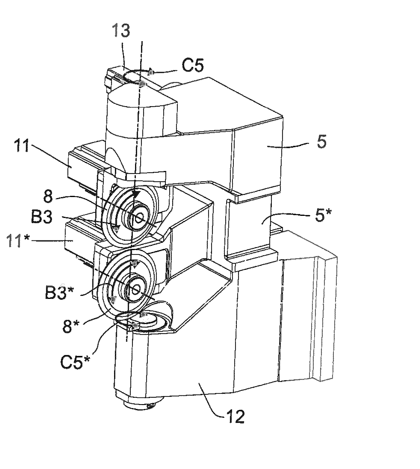
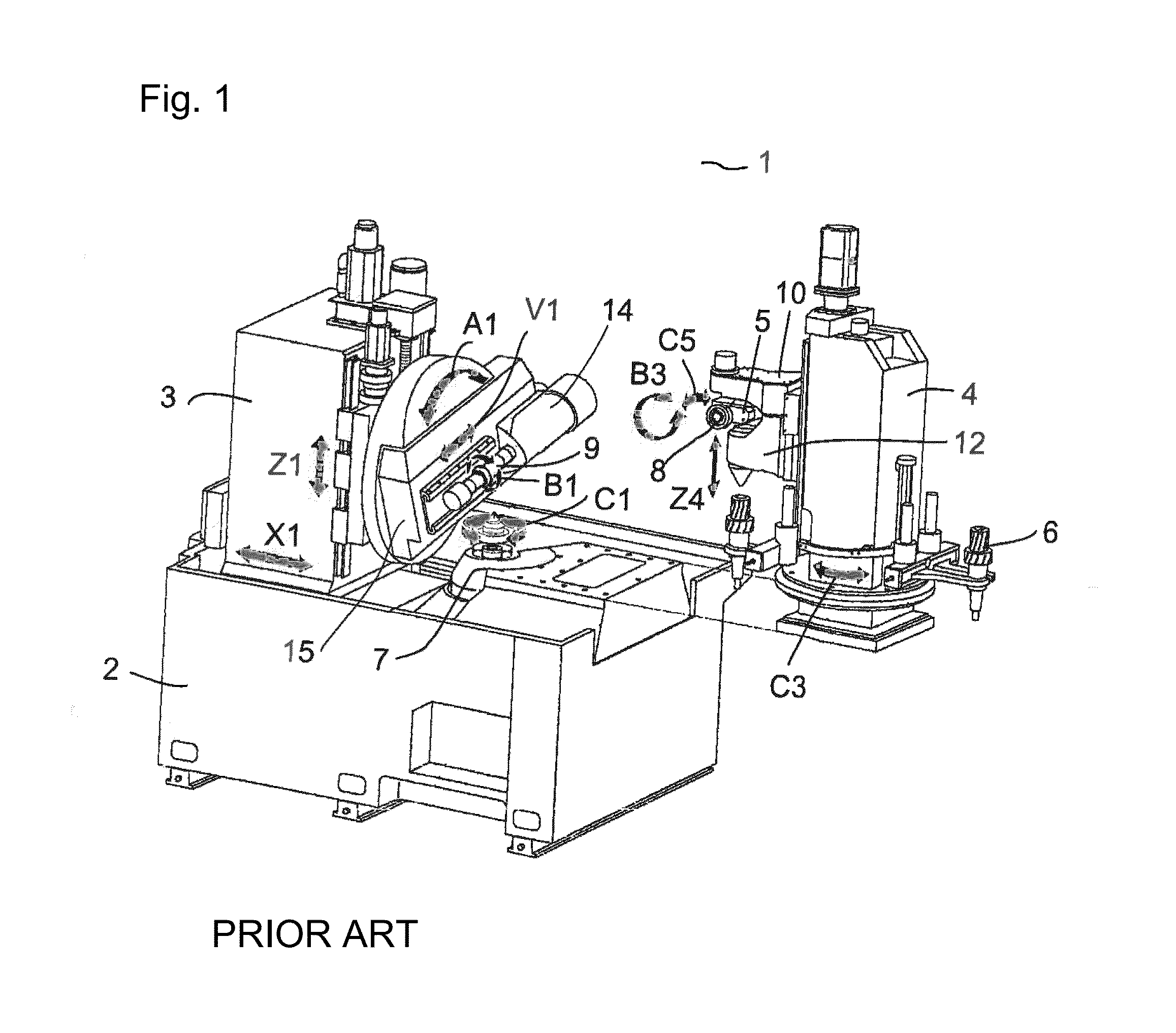
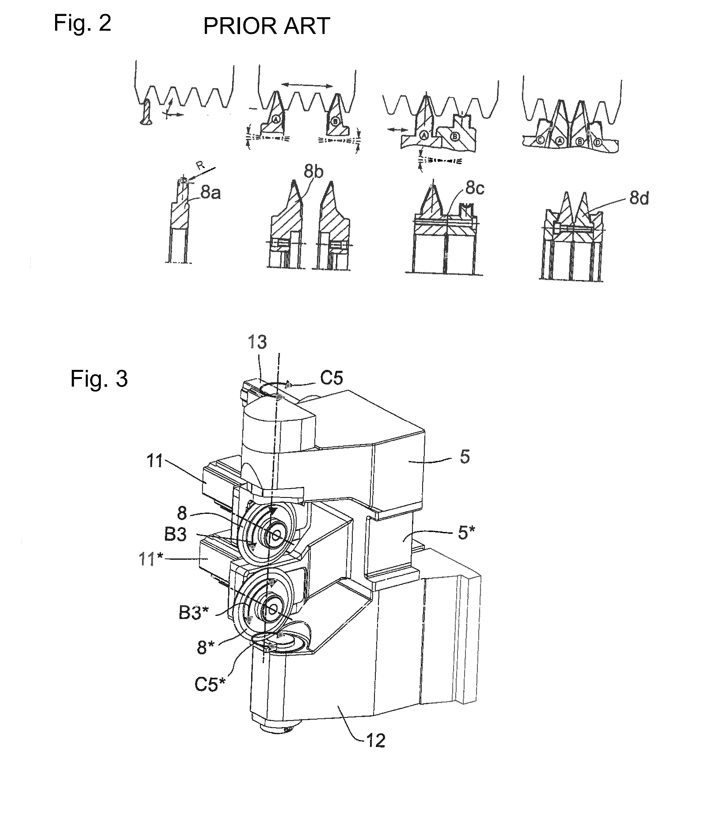
[0044]FIG. 1 shows a gear grinding machine 1 in accordance with the prior art on which, for example, a dressing apparatus in accordance with the present disclosure can be used. A machine table 7 which is provided for receiving workpieces 6 via a clamping apparatus (not shown) is mounted on a machine bed 2. The machine table 7 is in this respect rotatable about the axis C1 which is advantageously aligned perpendicular. Alternatively, however, horizontally aligned machine tables can also be used. The gear grinding machine furthermore has a machine stand 3 and a processing head 15 having a work spindle 14 for clamping a tool receiver 9. A counter-stand 4 is mounted opposite the machine stand 3 on the machine bed 2. A loading system having a pivot axis C3 is located on the counter-stand 3 and conveys the workpiece 6 from an external automated unit (not shown) to the machine table 7 or into the clamping apparatus mounted on the machine table. A counter-holder arm 12 is movable vertically...


PUM

PropertyMeasurementUnit
angleaaaaaaaaaa
diametersaaaaaaaaaa
surfaceaaaaaaaaaa

Abstract

The present disclosure relates to an apparatus and to a method for dressing generating grinding tools or profile grinding tools for the gear cutting processing of toothed workpieces using at least two disk-shaped dressing tools with which one or more tool regions and/or profile regions of the tool are provided with a defined dressing geometry.

Description

CROSS REFERENCE TO RELATED APPLICATION[0001]This application claims priority to German Patent Application No. 10 2013 011 048.3 entitled “Double-Side Dresser,” filed Jul. 2, 2013, which is hereby incorporated by reference in its entirety for all purposes.TECHNICAL FIELD[0002]The present disclosure relates to an apparatus and to a method for dressing generating grinding tools or profile grinding tools for the gear cutting processing of toothed workpieces using at least two disk-shaped dressing tools with which one or more tool regions and / or profile regions of the tool are provided with a defined dressing geometry.BACKGROUND AND SUMMARY[0003]Gear grinding machines are used in the manufacture of gears for the hard fine processing of preprocessed gears to give the latter their final geometry. As a rule, in this respect teeth are first shaped from a rotationally symmetrical workpiece, e.g. by cutting or shaping, in a soft preprocessing step in the manufacture of gears. The workpiece pre...

Claims


Application Information

Patent Timeline
Patent Type & Authority Applications(United States)
IPC IPC(8): B24B53/075B24B53/06
CPCB24B53/062B24B53/075B23F21/005B23F21/026B23F23/1225
Inventor BREITH, THOMASZANKL, MANFRED
Owner LIEBHERR VERZAHNTECHNIK GMBH
Why Eureka
Try Eureka