Vehicle lock and alarm

Inactive Publication Date: 2001-05-22
AIASHI
View PDF10 Cites 29 Cited by
  • Summary
  • Abstract
  • Description
  • Claims
  • Application Information

AI Technical Summary

Problems solved by technology

However, such locks of the prior art attach or include the alarm to or with the lock itself, and breaking the lock may destroy the alarm, or, the alarm can be covered with cloth to mute its volume and thereby reduce its ability to deter theft.
Further, since the alarm must emit sound as a warning, it is not possible to provide a completely sealed, waterproof structure.
Accordingly, moisture can enter the locking device and may deteriorate the lock or produce operational failure.
In addition, because the alarm requires relatively high electric power to operate and since there is lim

Method used


Image

  • Vehicle lock and alarm
  • Vehicle lock and alarm
  • Vehicle lock and alarm

Examples


Embodiment Construction

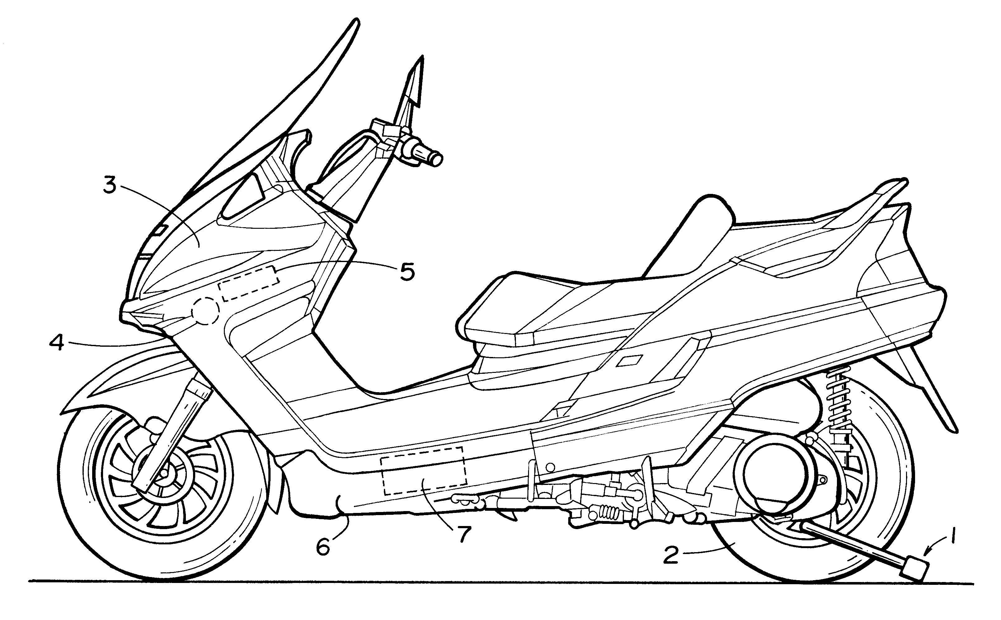
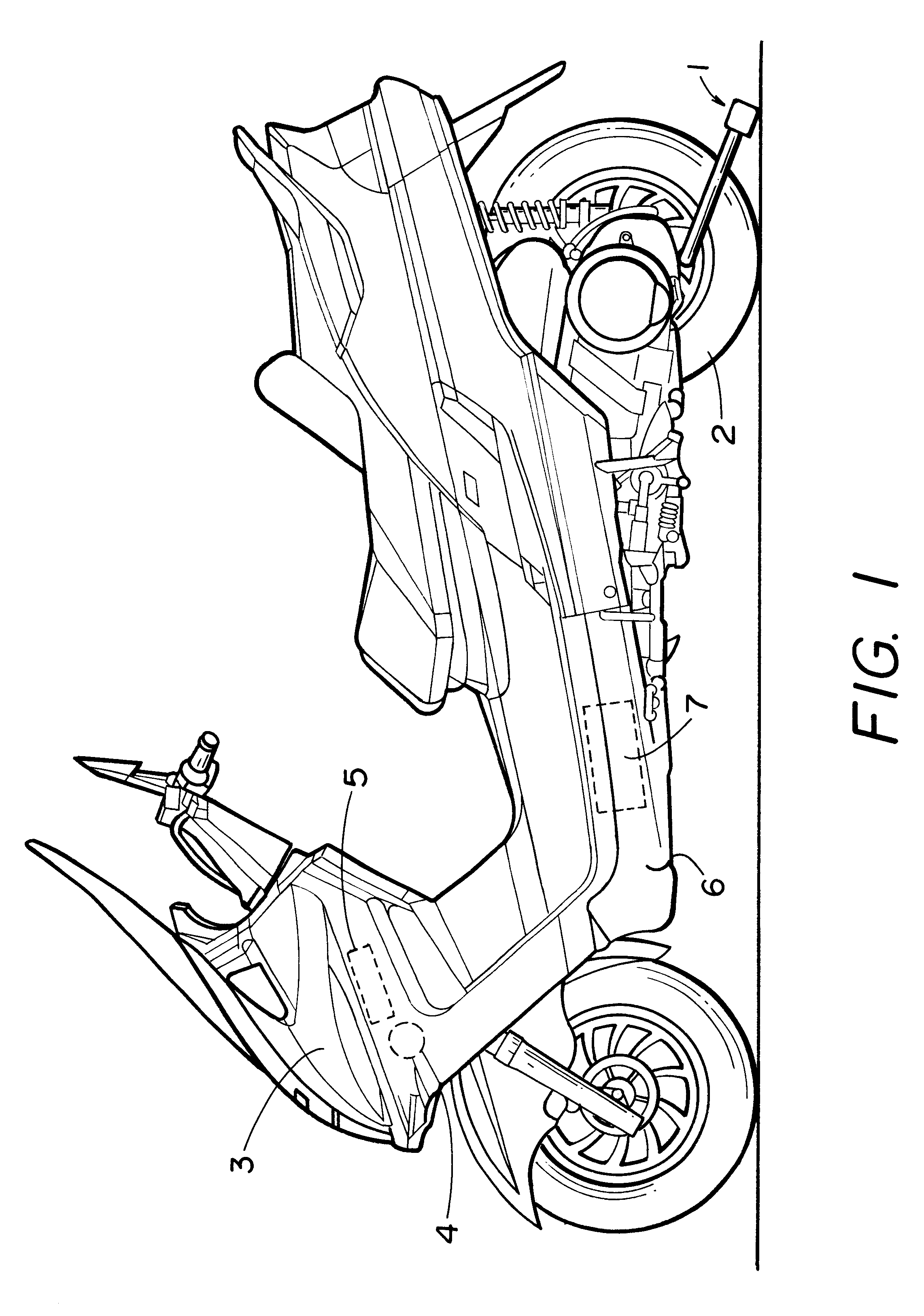
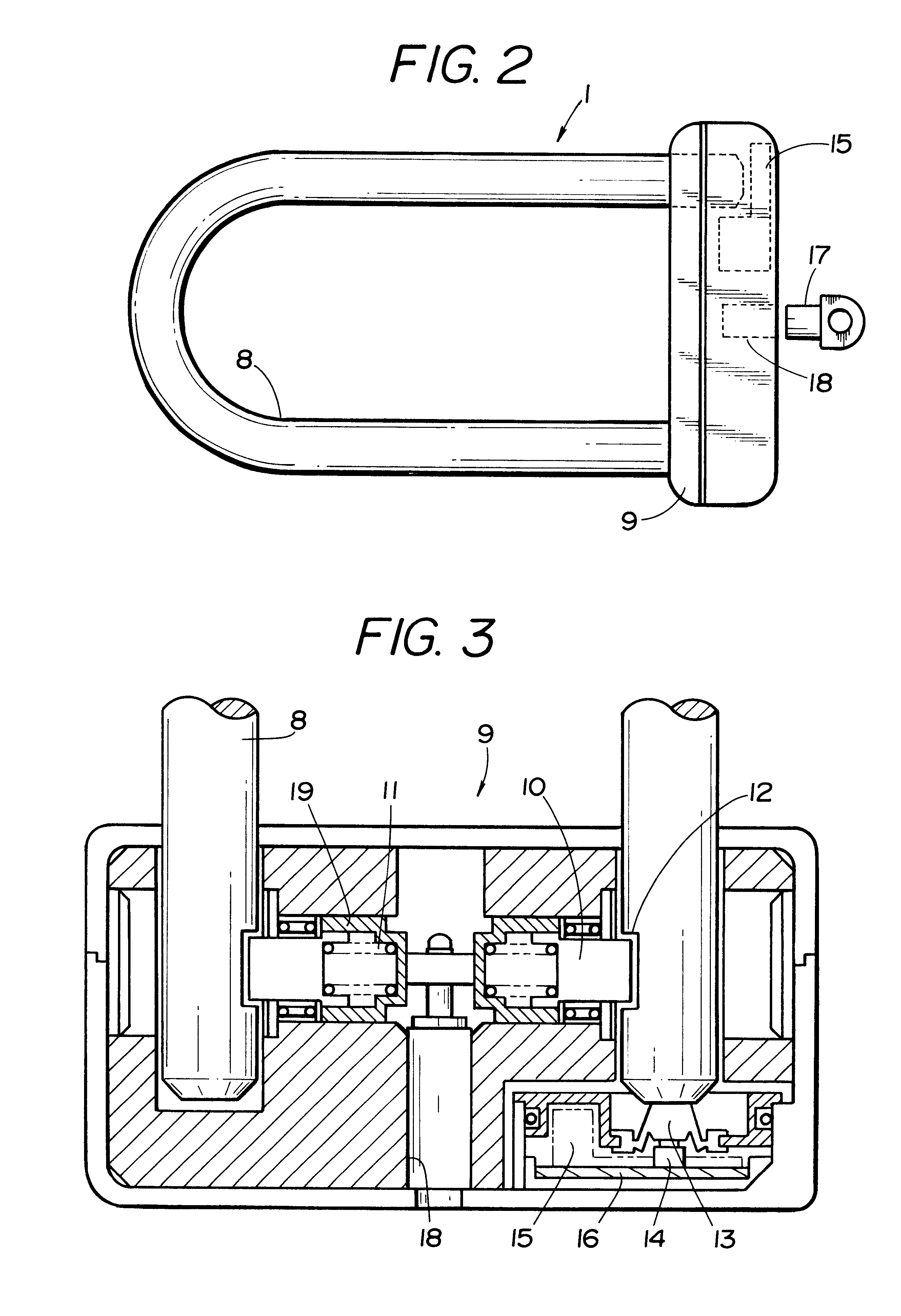
FIG. 1 shows an embodiment of a lock and alarm in accordance with this invention attached to a motorcycle. As shown in this figure, a padlock type lock 1 including a shackle or bar 8 (as shown in FIG.2) is attached to the wheel (rear wheel or driving wheel member) 2 to render it not freely rotatable. As will be described below, a conventional sensor that detects vibration or tilting of the lock and a transmitter of the type known to persons skilled in the art and that emits an alarm activating signal in response to motion detection are installed inside the lock. Preferably positioned within the vehicle fairing enclosure, there is an anti-theft alarm device 4 and a control unit 5 that operates the alarm device. As will be described below, the control unit 5 controls the power to the alarm device 4 based upon the receipt of an alarm activating signal by the receiver from the aforesaid transmitter. Thus, because it is easy to install the alarm device 4 in a place not visible from outsi...


PUM


Abstract

A vehicle alarm system for use with a lock (1) that is attachable to a vehicle wheel (2). The alarm system includes a lock motion detection sensor (20) and a transmitter (15) to transmit signals from the detection sensor. The motion detection sensor and the transmitter are located inside the lock. The vehicle includes a receiver (24) that receives the detection signals sent by the transmitter (15), an alarm (4) that emits a warning sound, and an operations control unit (25) that sounds the alarm in response to the signal from the receiver. The control unit and alarm are powered by the vehicle's battery (7).

Description

1. Field of the InventionThe present invention relates to locks which can be attached to vehicles such as motorcycles. More specifically, it relates to locks that incorporate an alarm system.2. Related ArtIn the prior art, locking devices have been attached to wheels of motorcycles and the like to prevent theft, including locks that were equipped with an alarm which would sound when the lock was moved. FIG. 6 is a simplified diagram of a conventional lock equipped with such an alarm. As is shown in the figure, when closed, the lock forms a U-shaped ring, and when it is installed around a vehicle wheel (not shown), the lock immobilizes the vehicle. After the vehicle has been parked, the approximately U-shaped shackle or bar 31 is attached through the inside of the wheel and then the left and right ends of the bar are inserted into a locking member body 32 located outside of the wheel. This locking member 32 is equipped with a sensor, alarm, and electronic parts to control them locate...

Claims


Application Information

Patent Timeline
IPC IPC(8): B60R25/10B62H5/00B62H5/20E05B45/00E05B45/06G08B13/00B60R25/30B62H5/16
CPCB60R25/1001B60R25/1004B60R25/1018B62H5/20E05B45/005B60R2325/306E05B45/06
Inventor KURANO, YOSHIAKI
Owner AIASHI
Why Eureka
Try Eureka