

Band and wrist device
a wristband and band technology, applied in the field of wristbands and wristbands, can solve the problems of cracks in the surface treated layer, easy falling off of metal members, and difficulty in obtaining the unity of the watch band
- Summary
- Abstract
- Description
- Claims
- Application Information
AI Technical Summary
Benefits of technology
Problems solved by technology
Method used
Image

Examples
first embodiment
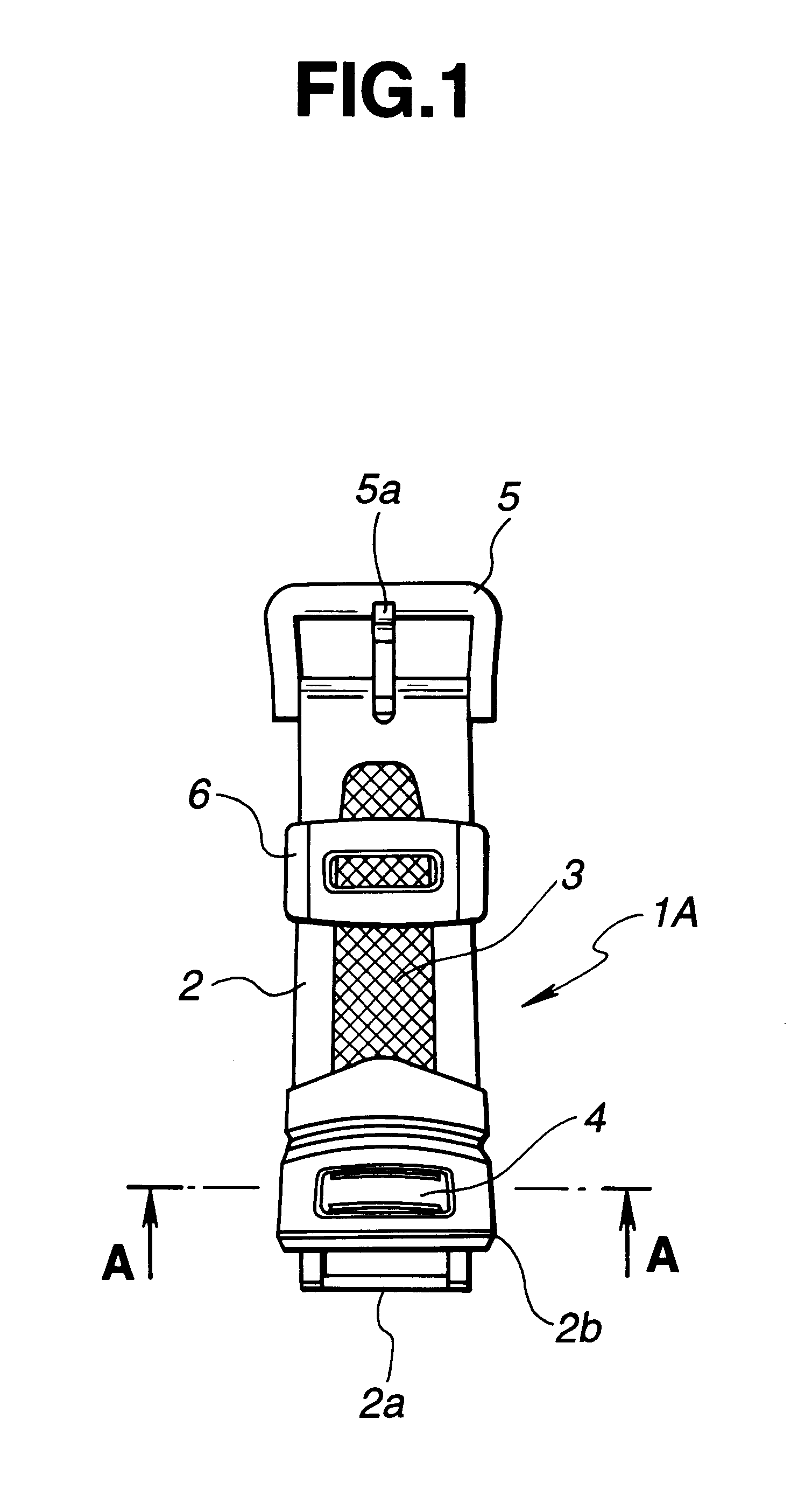
FIG. 1 is a plan view showing one half body of a watch band according to an example of the invention, and FIG. 2 is a plan view showing the other half body to be combined with the one half body.
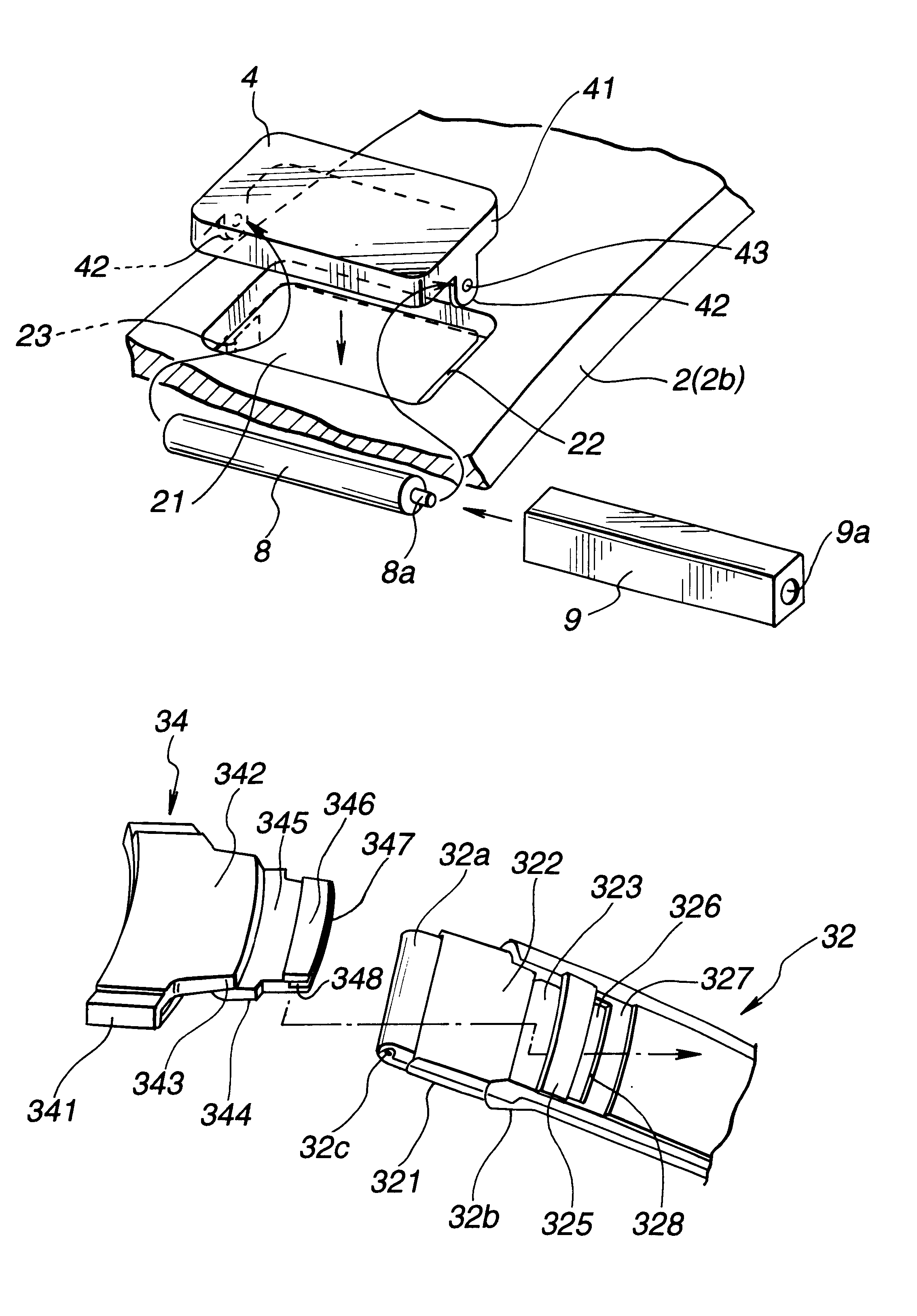
One half body 1A of a watch band, as shown in FIG. 1, comprises a band body 2 which is made of soft synthetic resin and made as a body with surrounding a fiber 3 made of nylon or the like. The band body 2 comprises a wide attaching portion 2b which is provided with an attaching boss 2a for attaching the band body 2 to a case complete which is not shown. A plate-like decorative member 4 which is made of metal is attached to a surface of the wide attaching portion 2b.
A holder 5 having a tongue 5a is attached to an end portion of the band body 2, which is an opposite side of the attaching portion 2b. The band body 2 is provided with a loop 6 in an intermediate portion thereof.
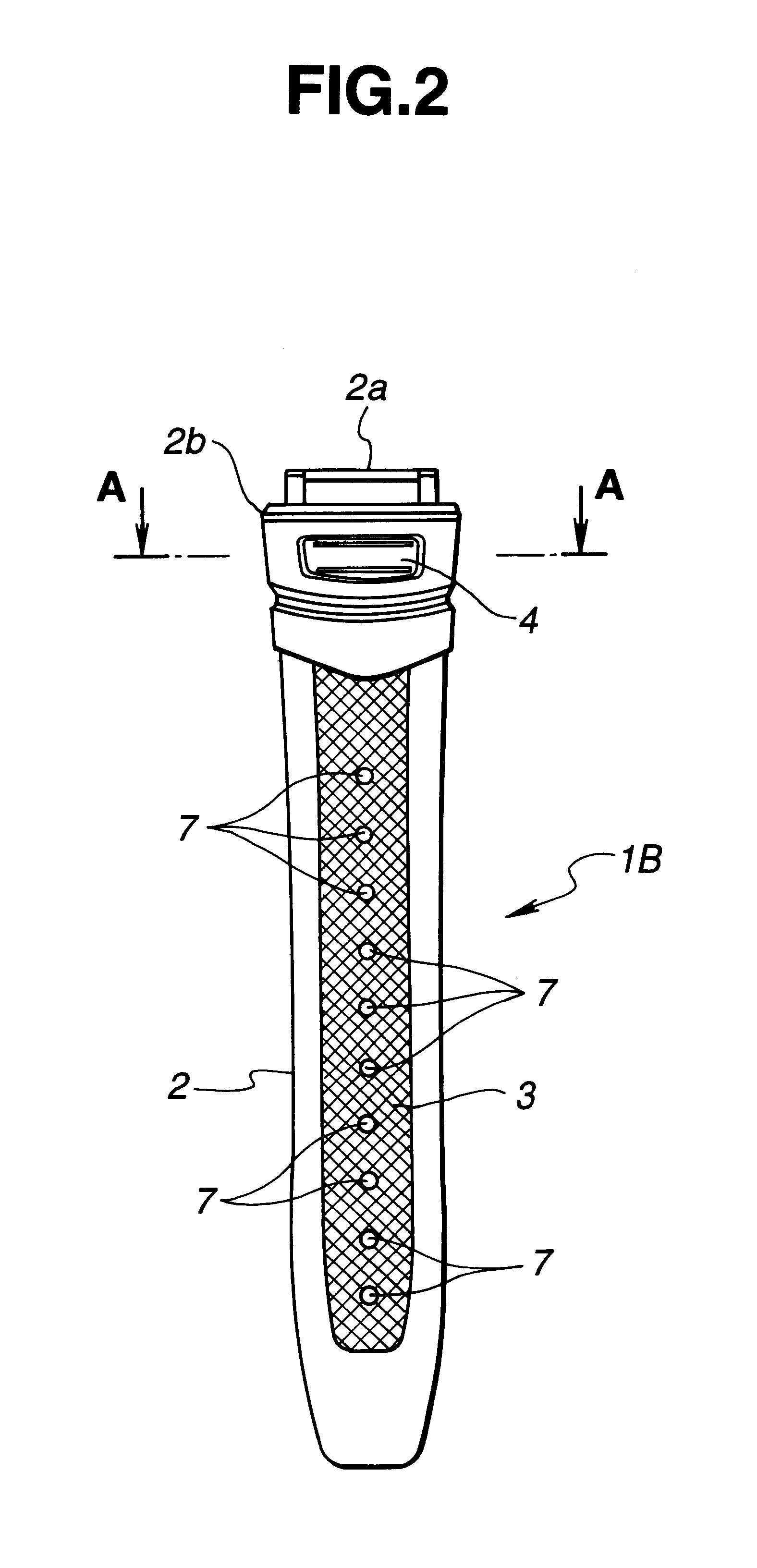
The other half body 1B of a watch band, as shown in FIG. 2, is used by being combined with the half body 1A shown in FIG....
second embodiment
The second embodiment is mainly different from the first embodiment in the structure of the covering member 10, so that only the difference will be explained as follows.
The covering member 10 has, as shown, a transversely oblong plate-like shape. The covering member 10 is made of soft synthetic resin in which the end bent tabs 10a and 10a in both end portions of the covering member and the pair of cut out ring-like portions 10b and 10b which are C-shaped in side view and engaging portions in intermediate portion are made as a body.
A length between the end bent tabs 10a and 10a in both end portions of the covering member 10 having the transversely oblong plate-like shape is made longer than a length of the bar-like member 8 having the spring bar, which contains the projecting portions 8a and 8a in the both end portions.
The rear side recess portion 24 of the band body 2 has, as shown, a length which is transversely longer than that of the first embodiment, as shown in FIG. 3.
In a case...
third embodiment
The third embodiment is mainly different from the first embodiment in the structure of the covering member 11, so that only the difference will be explained as follows.
The covering member 11 has, as shown, a transversely oblong cylindrical shape and is made of soft synthetic resin, in which the slit 11a is formed in a longitudinal direction thereof.
In a case that the covering member 11 is applied, as the second embodiment above-described, at first, the projecting portions 8a and 8a in the both end portions of the bar-like member 8 having the spring bar are inserted respectively into the small holes 43 and 43 of the inserting tab-like portions 42 and 42 of the decorative member 4 in the rear side recess portion 24 of the band body 2.
Thereafter, in the rear side recess portion 24 of the band body 2, as shown in FIG. 10 with arrows, the oblong cylindrical covering member 11 is pushed against the bar-like member 8 to open in the slit 11a and fitted around the bar-like member 8 having sp...
PUM
 Abstract
Description
Claims
Application Information