Filling transfer apparatus for bone cement

Inactive Publication Date: 2001-05-29
SULZER ORTHOPAEDIC
View PDF8 Cites 41 Cited by
  • Summary
  • Abstract
  • Description
  • Claims
  • Application Information

AI Technical Summary

Problems solved by technology

The latter however has the disadvantage that a filling transfer piston which is wetted by liquid bone cement must first be drawn out of a mixing conta

Method used


Image

  • Filling transfer apparatus for bone cement
  • Filling transfer apparatus for bone cement
  • Filling transfer apparatus for bone cement

Examples


Embodiment Construction

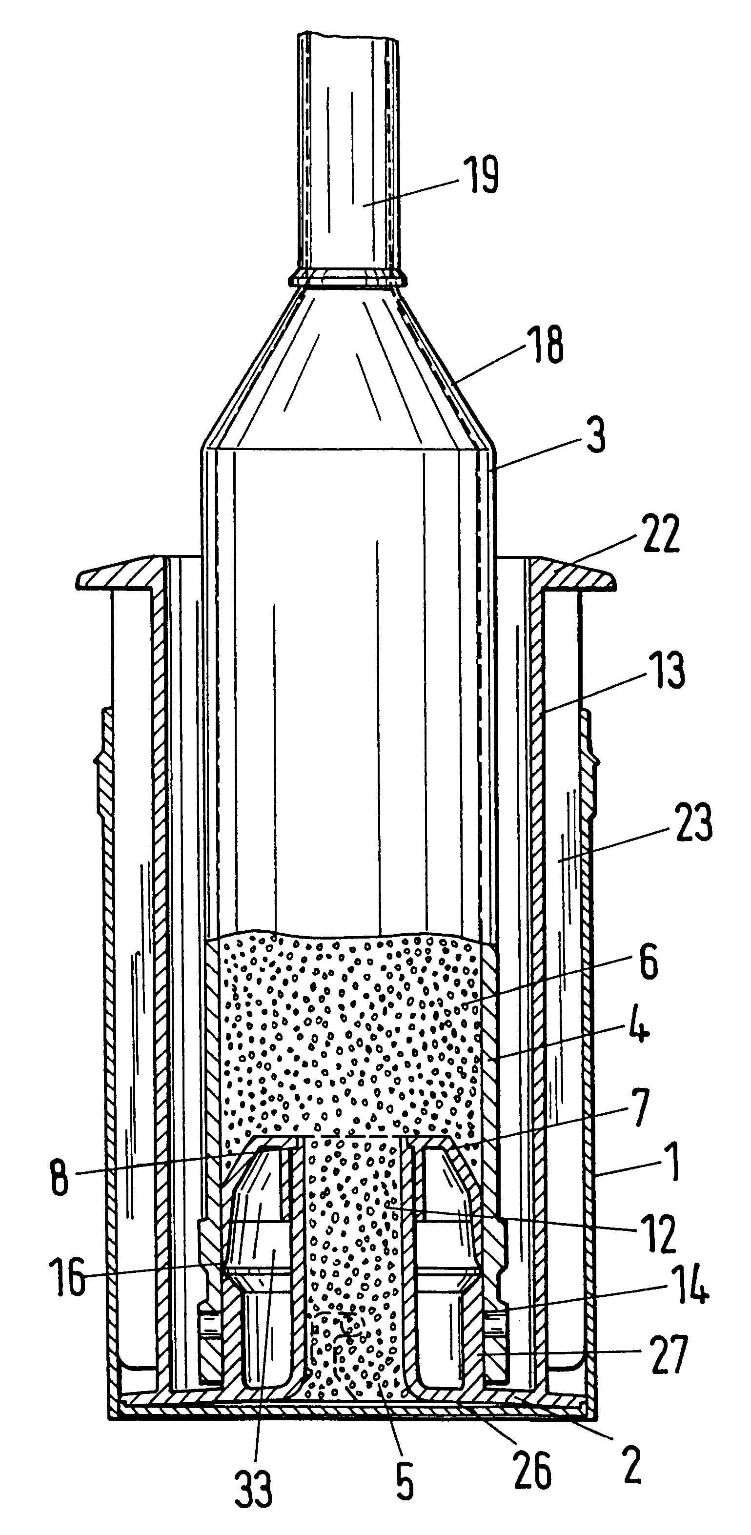
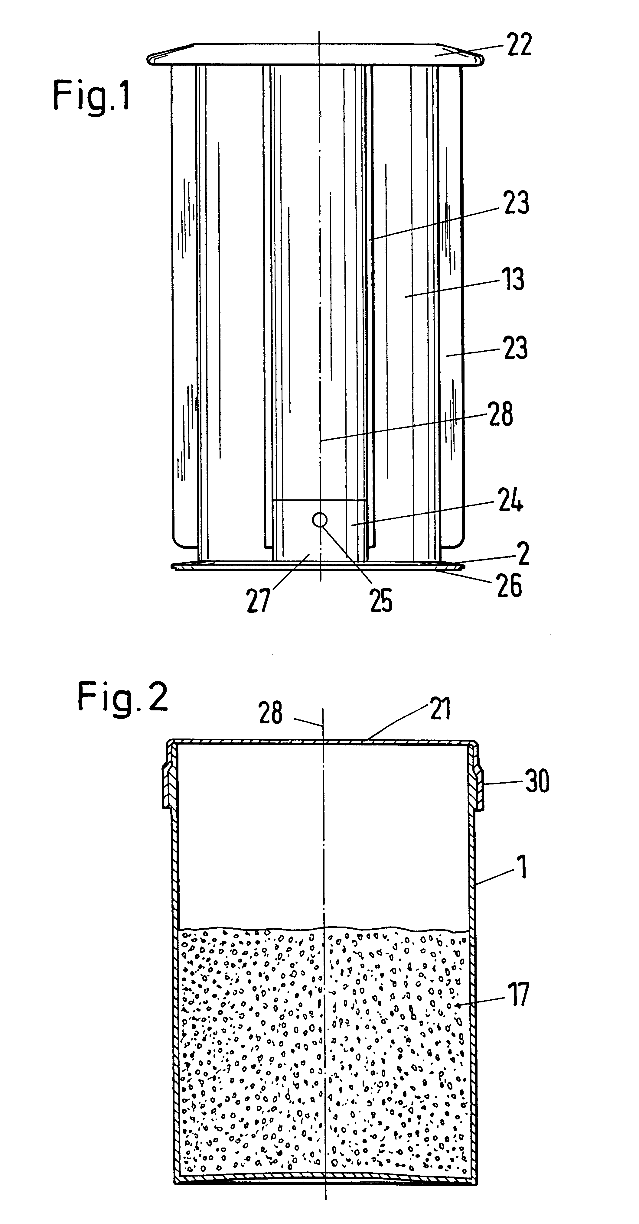
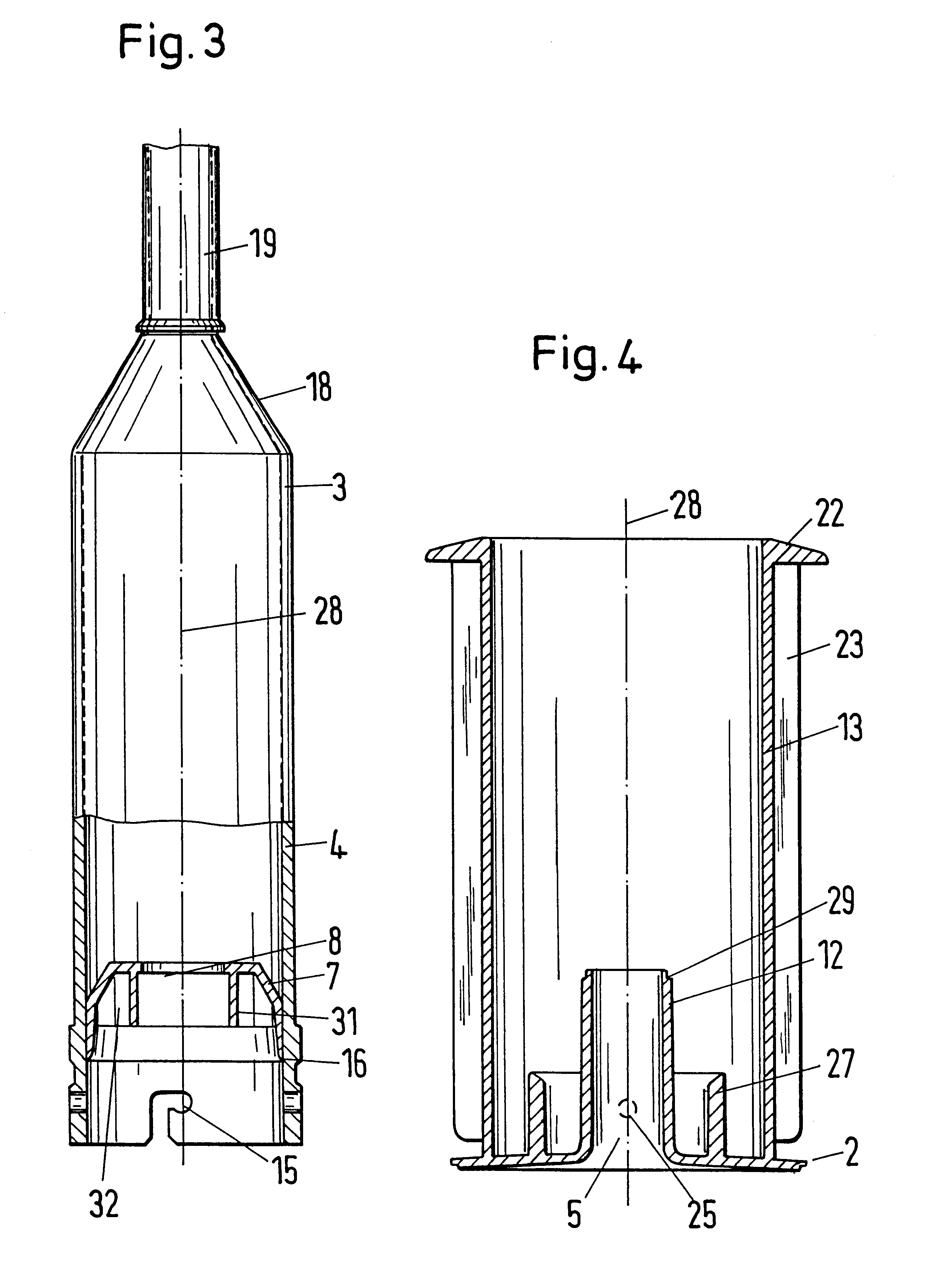
A filling transfer apparatus for bone cement with a cylindrical, upwardly open mixing container 1 and with a filling transfer piston 2 which can be inserted therein, which is removably connected to the sleeve 4 of a cement injector 3 and which has an opening 5 through which the mixed bone cement 6 can be transferred into the sleeve 4 through a pressing down of the filling transfer piston 2 is illustrated in the figures. Inserted in the sleeve 4 in this is an ejection piston 7 which has an aperture 8 in the region of the opening 5 for the through-flowing cement which can be closed with a plug after the removal of the cement injector 3.

The reference symbols in the figures are used for similar concepts. Since such parts as the mixing container 1, the lid 21, the filling transfer piston 2, the cement injector 3 with the sleeve 4 and with the ejection piston 7 are throw-away parts with large production numbers, these are as a rule manufactured of thermoplastics in injection moulding mach...


PUM


Abstract

The invention shows a filling transfer apparatus for bone cement with a cylindrical, upwardly open mixing container and a filling transfer piston which can be inserted therein, which is removably connected to the sleeve of a cement injector and which has an opening through which the mixed bone cement can be transferred into the sleeve through a pressing down of the filling transfer piston. In this an ejection piston is inserted in the sleeve and has an aperture in the region of the opening for the through-flowing cement which can be closed by a plug (9) after the removal of the cement injector.

Description

1. Field of the InventionThe invention relates to a filling transfer apparatus for bone cement with a cylindrical mixing container which is upwardly open and to a filling transfer piston which can be inserted therein, which is releasably connected to the sleeve of a cement injector and which has an opening through which the mixed bone cement can be transferred into the sleeve by a pressing down of the filling transfer piston.2. Description of the Prior ArtA filling transfer apparatus of this kind is described in detail in EP-A-0 261 182. The latter however has the disadvantage that a filling transfer piston which is wetted by liquid bone cement must first be drawn out of a mixing container and must be disconnected from the actual injector in order to place on an ejection piston corresponding to the inner crosssection of the injector. In this, liquid bone cement should neither be sucked backwards nor spilled nor distributed to the surroundings.The object of the invention is to improv...

Claims


Application Information

Patent Timeline
IPC IPC(8): A61F2/46B05C17/005B05C17/01A61B19/00A61F2/00A61B19/02A61B50/00B01F13/00
CPCA61B17/8825A61B17/8833B05C17/01A61B2017/8838A61B2019/0217A61B2019/0239A61F2002/30065A61F2002/30716A61F2002/4623A61F2210/0071A61F2250/009B01F2215/0029A61B2050/0063A61B2050/0083A61F2/4603B01F2101/20
Inventor HELLER, MATHIASSUAREZ, FERNANDO
Owner SULZER ORTHOPAEDIC
Why Eureka
Try Eureka