Exhaust silencer and communicating pipe thereof

a technology of exhaust silencer and communication pipe, which is applied in the direction of gas chamber, machine/engine, gas passage, etc., can solve the problems of deterioration at none-tuned frequency, affecting the design, and affecting the performance of the exhaust silencer

Inactive Publication Date: 2001-06-05
KOMATSU LTD
View PDF14 Cites 75 Cited by
  • Summary
  • Abstract
  • Description
  • Claims
  • Application Information

AI Technical Summary

Problems solved by technology

However, following disadvantage occurs in the multistage-expansion type exhaust silencer.
However, following problems occur in the resonant type exhaust silencer.
First, only specific frequency of the exhaust noise is damped in the resonant chamber and noise reduction for the entire range of the exhaust noise cannot be expected.
Since the resonant chamber has to be tuned for each type of the internal combustion engine, which complicates design and deteriorates at none-tuned frequency.
Further, since a large space is required for the exhaust silencer to have the resonant chamber, the size of the exhaust silencer itself has to be made large.
However, there can be following disadvantage in the above arrangement.
Though pressure loss of exhaust gas can be avoided at a high engine speed, damping effect covering entire sound range as in the multistage-

Method used


Image

  • Exhaust silencer and communicating pipe thereof
  • Exhaust silencer and communicating pipe thereof
  • Exhaust silencer and communicating pipe thereof

Examples


first embodiment

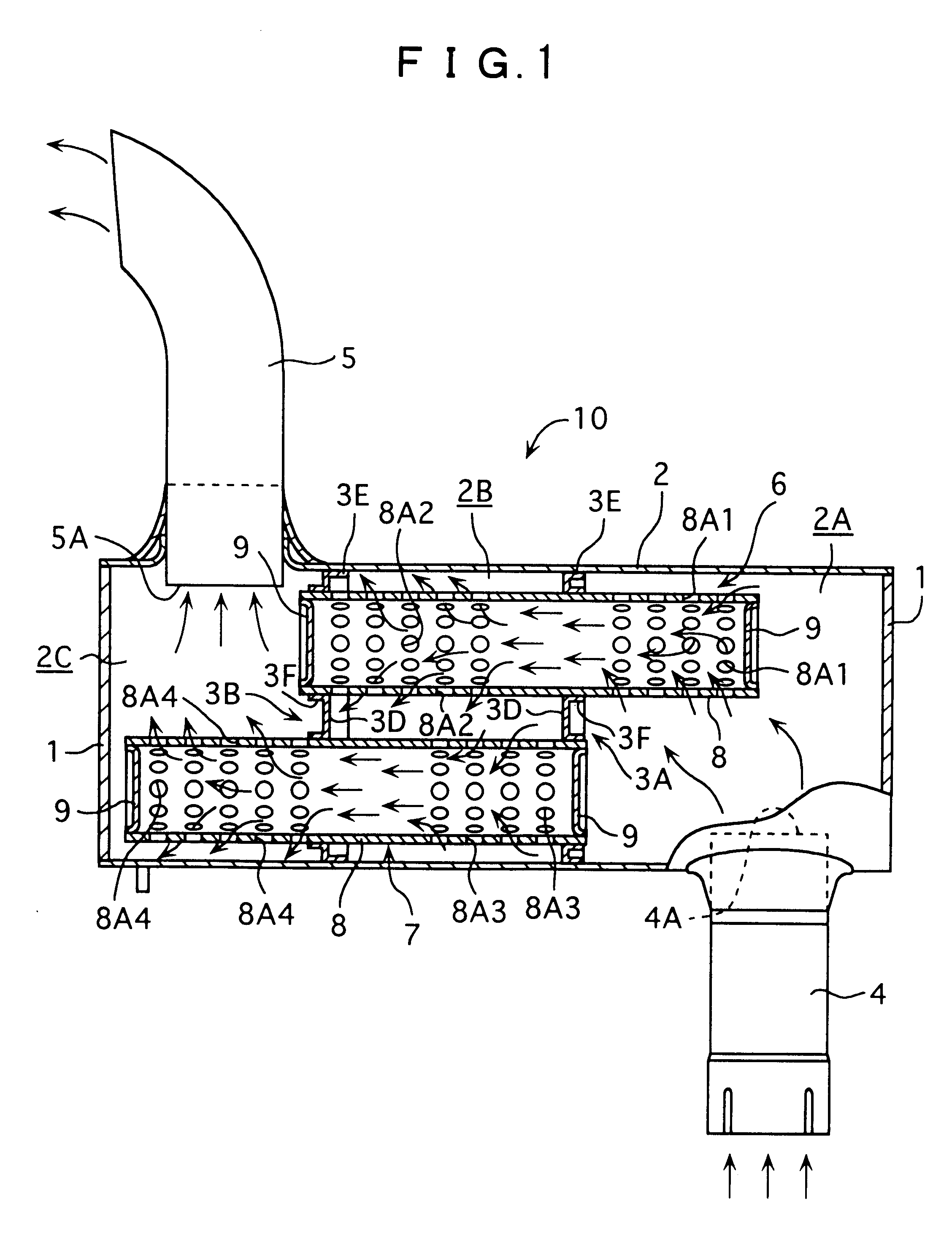
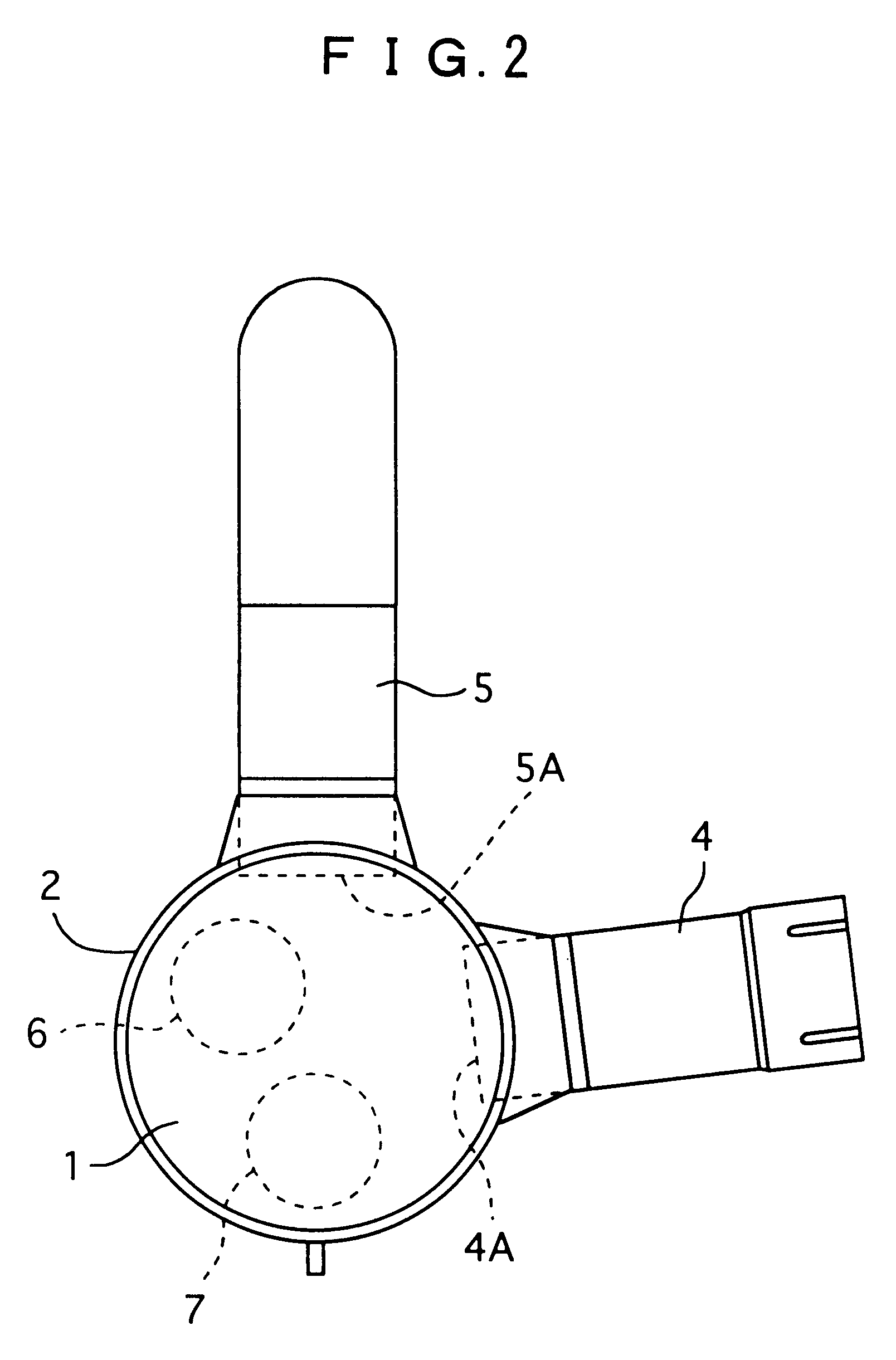
First embodiment of the present invention is shown in FIGS. 1 and 2.

In the figures, an exhaust silencer 10 of the first embodiment is connected to an exhaust pipe (not shown) of a diesel engine for construction equipment. The exhaust silencer 10 includes: a body 2 having a shape of both-end-bottomed cylinder having both ends being closed by end plates 1, i.e., drum-shape; first and second partitions 3A and 3B disposed parallel in an axial direction of the body 2 for partitioning the body 2 into first to third damping chambers 2A to 2C; an exhaust gas inlet pipe 4 in communication with the first damping chamber 2A and having the exhaust pipe connected thereto; a first damping chamber 2A and having the exhaust pipe connected thereto; a tail pipe 5 in communication with the third damping chamber 2C; first communicating pipe 6 with an intermediate portion being supported by the first partition 3A and an end being supported by the second partition 3B; and second communicating pipe 7 with...

second embodiment

The second embodiment differs from the first embodiment in that the communicating pipe is a single continuous communicating pipe, and the rest basic arrangement is the same as the first embodiment.

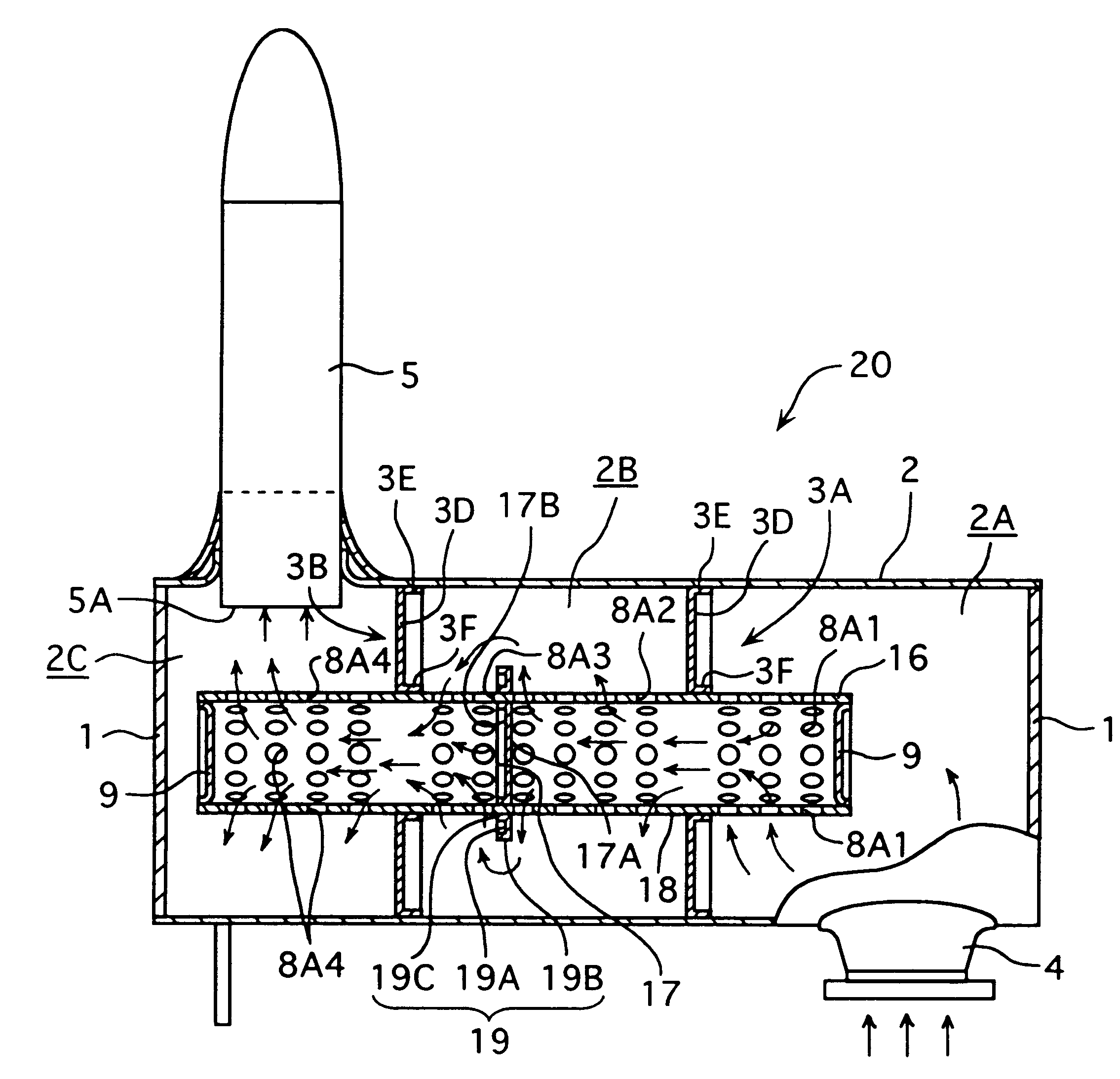
In FIG. 3 showing entire structure, the exhaust silencer 20 of the second embodiment has a drum-shaped body 2, first and second partitions 3A and 3B for partitioning the body 2 into the first to third damping chamber 2A to 2C, an exhaust gas inlet pipe 4 provided to the body 2, a tail pipe 5 provided to the body 2, a communicating pipe 16 supported by the first partition 3A and the second partition 3B respectively, a cutoff partition 17 provided to an axially intermediate position of the communicating pipe 16 corresponding to intermediary of the second damping chamber 2B, and a partitioning wall 19 provided to an outer circumference of the cutoff partition 17.

The communicating pipe 16 is composed of a cylindrical member 18 having an axis parallel to the axial direction of the body 2, and e...

third embodiment

The third embodiment is a variation of the second embodiment.

In FIG. 4 showing the entire structure, the exhaust silencer 30 of the third embodiment has a body 2 divided into first to fourth damping chambers 2A to 2D by first to third partitions 3A to 3C, a substantially single communicating pipe 26 supported by the partitions 3A to 3C, and first and second partitioning member 29A and 29B.

The third partition 3C has the same structure as the first and the second partitions 3A and 3B.

The communicating pipe 26 has first to third cylindrical member 28A to 28C, an end plate 9 disposed to one end of the first cylindrical member 28A and the third cylindrical member 28C. The first partitioning member 29A is inserted between the other end of the first cylindrical member 28A and one end of the second cylindrical member 28B, and the second partitioning member 29B is inserted between the other end of the second cylindrical member and the other end of the cylindrical member 28C.

The partitioning ...


PUM


Abstract

More than two damping chambers 2A to 2C), a communicating pipe (6) for intercommunicating the damping chambers (2A, 2B) and another communicating pipe (7) for intercommunicating the damping chambers (2B, 2C) are provided. Both ends of the communicating pipes (6, 7) are closed by an end plate (9) and the respective damping chambers (2A to 2C) and inside of the communicating pipes (6, 7) are intercommunicated by communicating holes (8A) on an outer circumference of the communicating pipes (6, 7). Exhaust gas flows from the damping chamber (2A) to communicating holes (8A1), inside of the communicating pipe (6), communicating holes (8A2), the damping chamber (2B), communicating holes (8A3), inside of the communicating pipe (7), communicating holes (8A4), and the damping chamber (2C), thus damping exhaust noise by repeated effective contraction and expansion.

Description

1. Field of the InventionThe present invention relates to an exhaust silencer of an internal combustion engine used for construction equipment and the like and a communicating pipe thereof.2. Description of Related ArtAn exhaust silencer called a "muffler" is connected to an exhaust pipe of an internal combustion engine used for a construction equipment etc. for reducing exhaust noise from a combustion chamber.Conventionally, various arrangements are known for the exhaust silencer. In an internal combustion engine of construction equipment, a multistage-expansion type in which sound is damped by repeating contraction and expansion of exhaust gas and a resonant type in which the exhaust gas is resonated for damping sound are known as conventional examples of the exhaust silencer.A conventional example of the multistage-expansion type exhaust silencer is shown in FIG. 15.In FIG. 15, the conventional exhaust silencer 100 has three partitions 52A to 52C aligned in an axial direction for...

Claims


Application Information

Patent Timeline
IPC IPC(8): F01N1/08
CPCF01N1/083F01N1/089F01N2470/02F01N2470/18F01N2470/24F01N2490/10
Inventor NISHIYAMA, TOSHIHIKOKATAYAMA, RIE
Owner KOMATSU LTD
Why Eureka
Try Eureka