Glass antenna device for an automobile

a technology for antenna devices and automobiles, applied in the direction of antennas, antenna details, antennas, etc., can solve the problems of poor s/n ratio, insufficient receiving sensitivity, insufficient signal receiving sensitivity and directivity for fm broadcast,

Inactive Publication Date: 2001-06-05
ASAHI GLASS CO LTD
View PDF19 Cites 27 Cited by
  • Summary
  • Abstract
  • Description
  • Claims
  • Application Information

AI Technical Summary

Problems solved by technology

Further, the S / N ratio was poor because the parallel resonance frequency existed in a middle broadcast band, and the receiving sensitivity was insufficient because the resonance occurred in a single portion.
Further, when the defogger 90 was utilized as an antenna commonly used for a middle wave broadcast band and FM broadcast band and even when the shape of the defogger 90 was optimized for receiving middle wave broadcast signals, there were problems that the signal receiving sensitivity and the directivity for a FM broadcast were insufficient in a case of receiving middle wave broadcast signals.
When the above-mentioned resonance frequencies are out of these ranges, it is difficult that a difference between the highest signal receiving sensitivity and the lowest signal receiving sensitivity in the low frequency band is generally about 10 dB or less, and the flatness in the signal receiving sensitivity in the low frequency band is poor.

Method used


Image

  • Glass antenna device for an automobile
  • Glass antenna device for an automobile
  • Glass antenna device for an automobile

Examples


example 3

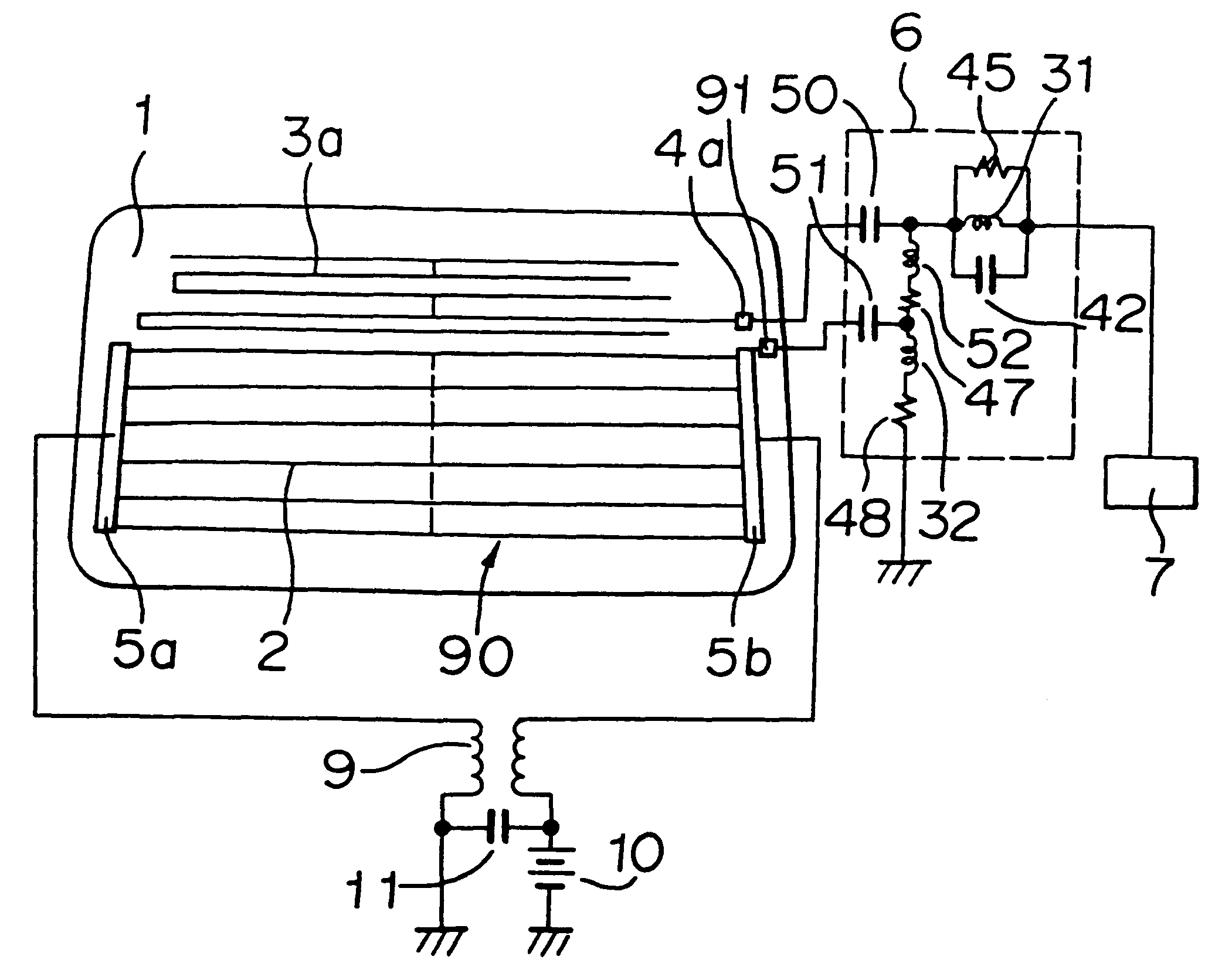
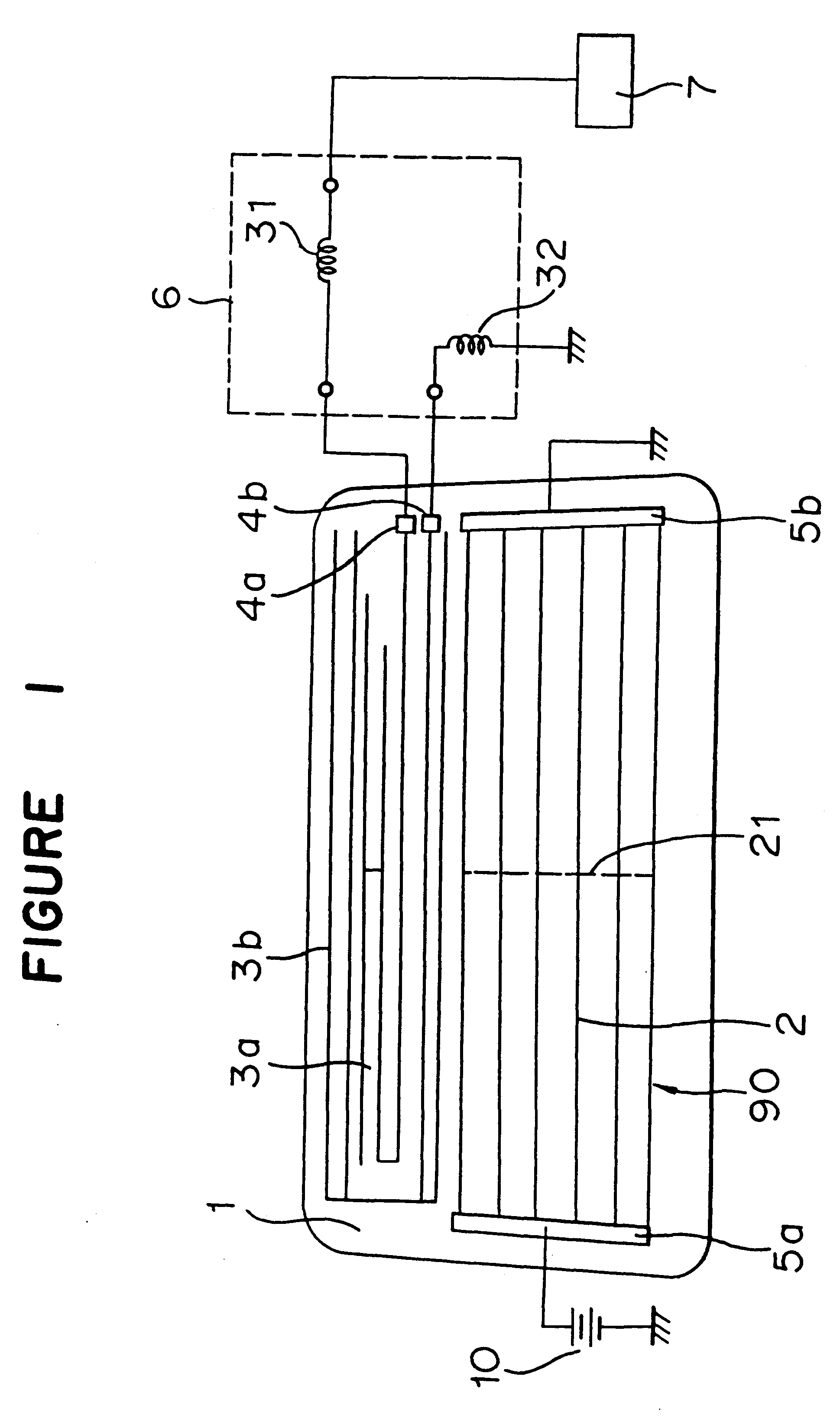
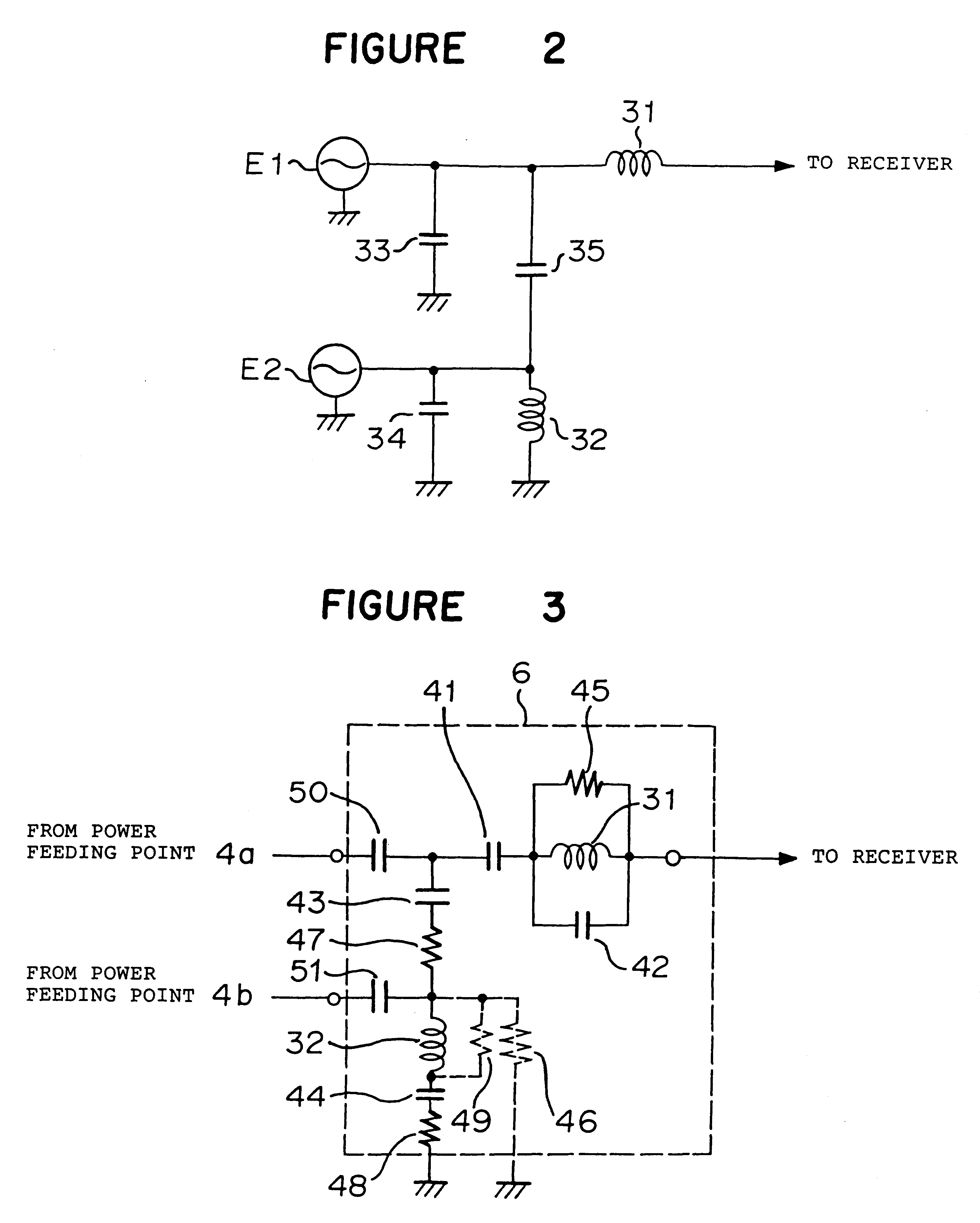
The glass antenna device as shown in FIG. 1 was formed in a rear window glass sheet of automobile. The same resonance circuit 6 as in FIG. 6 was employed wherein the capacitors 50 and 51 and resistors 46, 48 and 49 were not provided (the resistors 46 and 49 were opened; the resistor 48 was shortcircuited and the capacitors 50 and 51 were shortcircuited). With respect to the elements used, the same circuit constants as in Example 1 were used except for the first coil 31, the coil 52 and the resistor 47. The circuit constants of these elements were as follows. In FIG. 11, a solid line shows a result of the measurement of the FM broadcast band sensitivity in Example 3.

First coil 31: 120 .mu.H

High frequency choke coil 52: 2.7 .mu.H

Resistor 47: 220.OMEGA.

example 4

The glass antenna device as shown in FIG. 1 was formed in the same manner as in Example 3 except that the high frequency choke coil was not provided. In FIG. 11, a dotted line shows a result of the measurement of the FM broadcast band sensitivity of Example 4.

example 5

The glass antenna device as shown in FIG. 9 was formed in a rear window glass sheet of automobile wherein the first antenna conductor 3a, the second antenna conductor 3b and the defogger 90 were the same as those in Example 1. The same resonance circuit 6 as in FIG. 6 was employed wherein the capacitors 41 and 44 and the resistors 46 and 48 were not provided (the resistor 46 was opened, the capacitors 41 and 44 and the resistors 48 were shortcircuited).

A high frequency choke coil of 2.2 .mu.H was connected in series to the second coil 32. No high frequency choke coils 12a, 12b were not provided. The shortest distance between the second antenna conductor 3b and the defogger 90 was 10 mm, and the coupling capacitance between the second antenna conductor 3b and the defogger 90 was 80 pF. The circuit constants of the elements used were as follows.

First coil 31: 150 .mu.H

Second coil 32; 680 .mu.H

Capacitors 50, 51: 1000 pF

Coil 52: 2.2 .mu.H

Resistor 47: 270.OMEGA.

Resistor 49: 10k.OMEGA.

Res...


PUM


Abstract

A first resonance is generated by the inductance of a first coil connected between a first antenna conductor in a window glass sheet and a receiver and the impedance of the antenna conductor, and a second resonance is generated by the inductance of a second coil connected between a second antenna conductor 3b and an automobile body as the earth. The antenna conductor and the antenna conductor are in a capacitive coupling relation, whereby signals in different broadcast band: a low frequency band and a high frequency band, are well received.

Description

The present invention relates to a glass antenna device for an automobile suitable for received signals in a long wave broadcast band (LW band)(150-280 kHz), a middle wave broadcast band (530-1630 kHz), a short wave broadcast band (SW band)(2.3-26.1 MHz), an FM broadcast band (76-90 MHz, (Japan)), an FM broadcast band (88-108 MHz (U.S.A.)), a TV-VHF band (90-108 MHz and 170-222 MHz) and a TV-UHF band (470-770 MHZ), which has a high signal receiving sensitivity and a noise suppressing property and which is rich in productivity.DISCUSSION OF THE BACKGROUNDAs a glass antenna device for an automobile which is capable of improving the signal receiving sensitivity by utilizing resonance, there has been proposed a glass antenna device for an automobile as shown in FIG. 7 (JP-Y-4-53070).In this conventional example, a defogger 90 comprising heater strips 2 and bus bars 15a, 15b, 15c is provided in a rear window glass sheet 1 of an automobile, a choke coil 9 is connected between the bus bars...

Claims


Application Information

Patent Timeline
Patent Type & Authority Patents(United States)
IPC IPC(8): H01Q1/12H01Q1/32
CPCH01Q1/1271H01Q1/32
Inventor TERASHIMA, FUMITAKATABATA, KOHJIYAMAMOTO, TSUYOSHI
Owner ASAHI GLASS CO LTD
Why Eureka
Try Eureka