Tool and insert for chip removal machining

a technology for removing machining and cutting inserts, which is applied in the direction of milling cutters, milling equipment, turning apparatus, etc., can solve the problems of incorrect inserting of cutting inserts, high demands on the manufacturing of grooved parts, and cutting inserts being incorrectly positioned in the holder, etc., and achieves great resistance to extraction

Inactive Publication Date: 2001-06-12
SECO TOOLS AB
View PDF21 Cites 94 Cited by
  • Summary
  • Abstract
  • Description
  • Claims
  • Application Information

AI Technical Summary

Benefits of technology

Still another object of the present invention is to provide a tool and a cutting insert where the clamping force is distributed on such a large area that the cutting insert does not risk splitting.
Still another object of the present invention is to provide a tool and a cutting insert where twisting of the cutting insert under machining is avoided.
Still another object of the present invention is to provide a tool and a cutting ins

Problems solved by technology

With the known tool it is a danger that the cutting insert is inserted incorrectly, that may be the cutting insert can be inserted into the seat but incorrectly positioned in the lateral direction of the cuttin

Method used


Image

  • Tool and insert for chip removal machining
  • Tool and insert for chip removal machining
  • Tool and insert for chip removal machining

Examples


Embodiment Construction

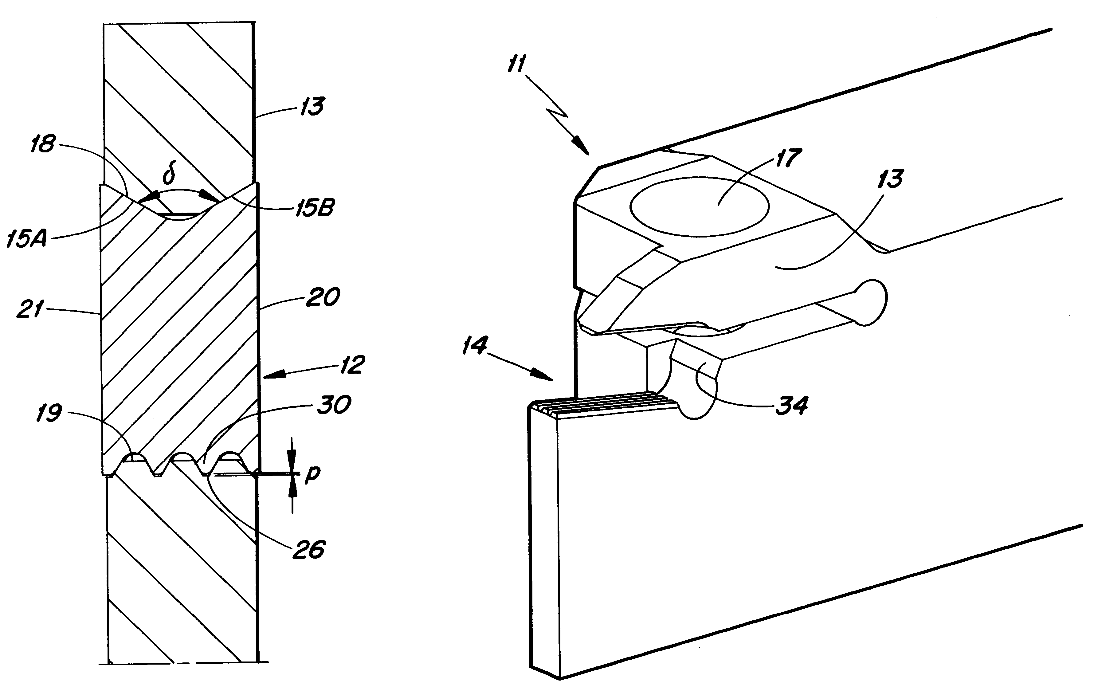
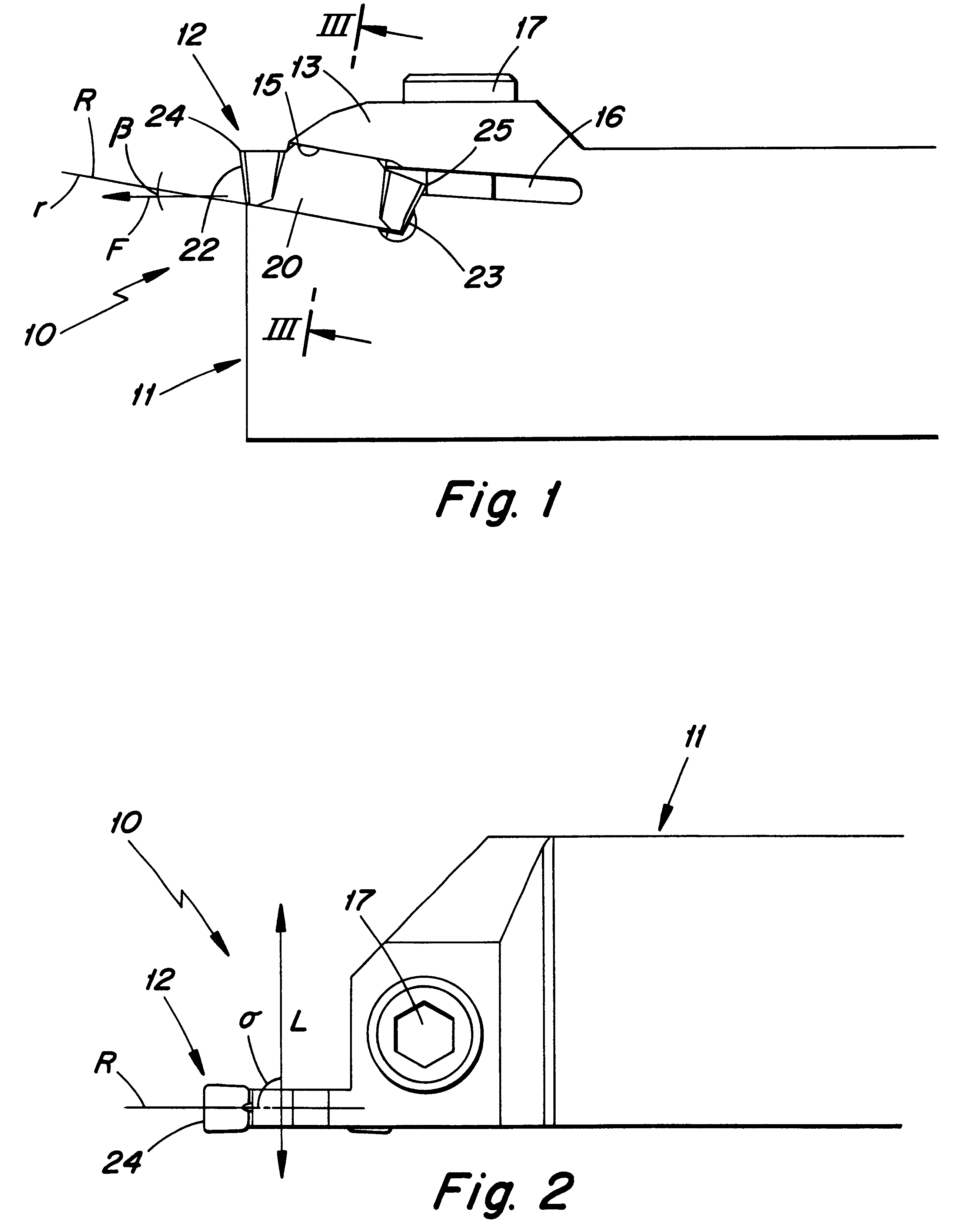
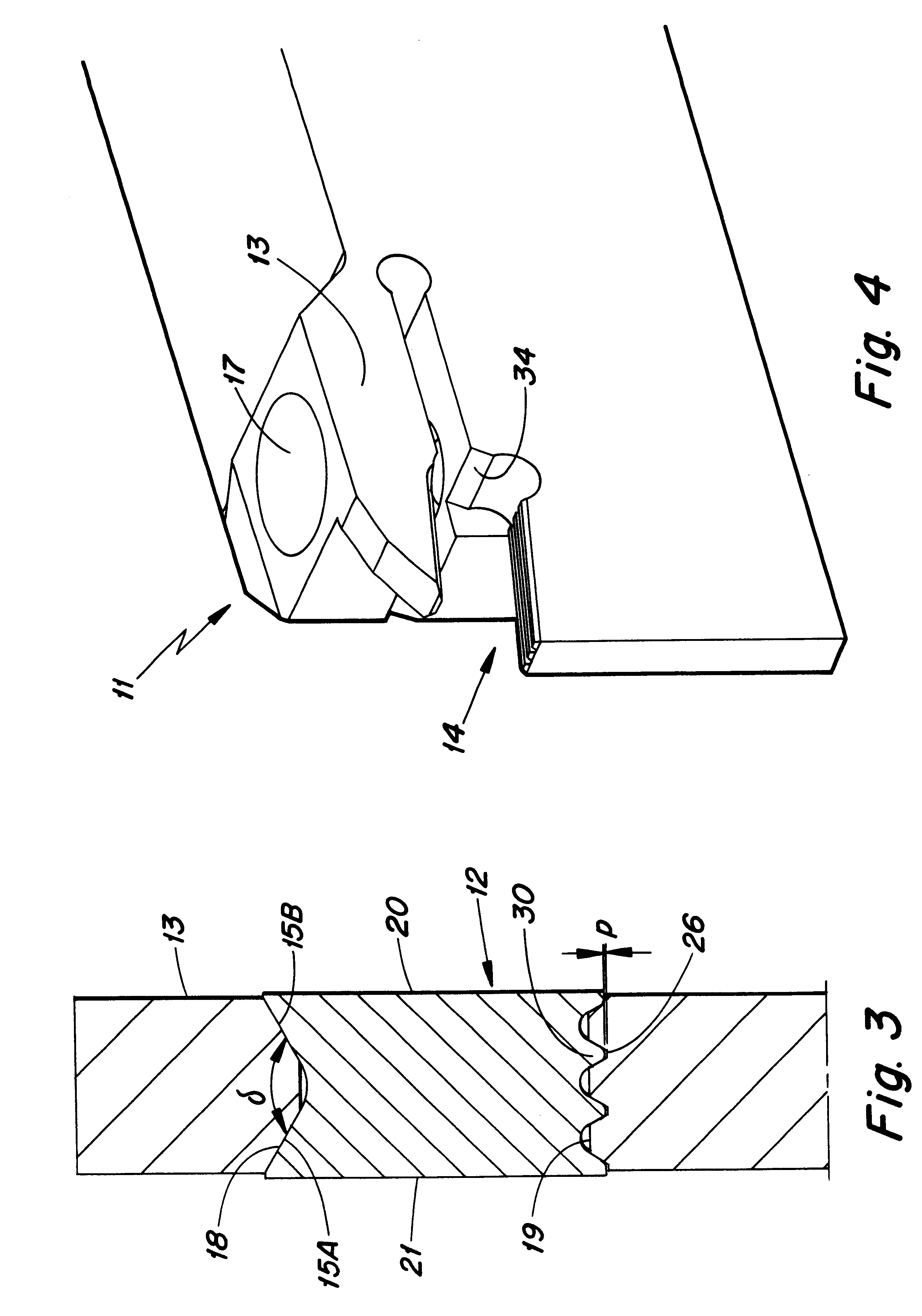
With reference to FIGS. 1-8 there is shown a tool 10, including a holder 11 and a cutting insert 12. The holder 11 is of the type where an arm 13 constitutes an upper side 15 of the insert pocket 14. The arm is movable by means of a slot 16 being provided to terminate in the cutting insert pocket. The slot extends in the longitudinal direction of the cutting insert, an appropriate distance, past a screw 17 influencing the arm. An abutment surface 34 is provided in connection with the lower border line of the slot 16, wherein the surface 34 constitutes a stop for the cutting insert in its longitudinal direction. The upper side 15 is of conventional geometry, that is, it has a general V-shape with flanks 15A, 15B converging towards the cutting insert. The flanks form a obtuse, inner angle .delta. with each other, which lies in the interval 120.degree. to 160.degree.. A clearance surface is provided between the flanks in order to avoid a central contact with the cutting insert. The arm...


PUM

PropertyMeasurementUnit
Fractionaaaaaaaaaa
Fractionaaaaaaaaaa
Angleaaaaaaaaaa

Abstract

A tool for chip removing machining includes a holder and a cutting insert clamped within a pocket of the holder. The pocket has upper and lower sides, and the cutting insert comprises an upper surface and a lower surface. The upper side of the pocket and the upper surface of the cutting insert comprise first cooperating contact surfaces defining a first flank angle. The lower side of the pocket and the lower surface of the cutting insert comprise second cooperating contact surfaces which define a second flank angle. The first flank angle is larger than the second flank angle. The lower surface of the cutting insert and the lower side of the pocket form intermeshing projections and recesses which define the second contact surfaces.

Description

THE FIELD OF THE INVENTIONThe present invention relates to a tool and a cutting insert for chip removing machining, preferably for grooving or slot milling. The tool comprises a holder and a cutting insert. The holder comprises at least a cutting insert pocket, which has an upper side and a lower side. The cutting insert comprises an upper surface and a lower surface. The upper side of the cutting insert pocket and the upper surface of the cutting insert comprise first cooperating contact surfaces, which define a first flank angle. The lower side of the cutting insert pocket and the lower surface of the cutting insert comprise second cooperating contact surfaces, which defines at least a second flank angle.PRIOR ARTIn U.S. Pat. No. 5,112,164 there is, concisely, described a tool of the above mentioned type. The cutting insert and the holder have cooperating grooved surfaces, wherein the first and second flank angles are identical. With the known tool it is a danger that the cutting ...

Claims


Application Information

Patent Timeline
IPC IPC(8): B23B27/04B23B27/00B23C5/20B23B27/16B23C5/22
CPCB23B27/045B23B2205/02B23B2260/124Y10T407/2288Y10T407/2284Y10T407/25B23B2260/132
Inventor KINGDOM, MIKE J.NIEMI, MATTI
Owner SECO TOOLS AB
Why Eureka
Try Eureka