Polymer cutting apparatus and method

Inactive Publication Date: 2001-06-19
EI DU PONT DE NEMOURS & CO
View PDF18 Cites 20 Cited by
  • Summary
  • Abstract
  • Description
  • Claims
  • Application Information

AI Technical Summary

Problems solved by technology

Among these is cutter knife breakage and / or wear, especially when hard and / or abrasive polymers are being cut.
It is believed that when knives with sharp acute cutting angles are used, the small amount of metal at the cutting edge makes that edge relatively weak and prone to breakage and / or relatively fast wear.
When breakage or excessive wear occurs, the cut quality is adversely affected, and the cutter must be shut down to resharpen or replace the worn or broken blades.

Method used


Image

  • Polymer cutting apparatus and method
  • Polymer cutting apparatus and method
  • Polymer cutting apparatus and method

Examples


example

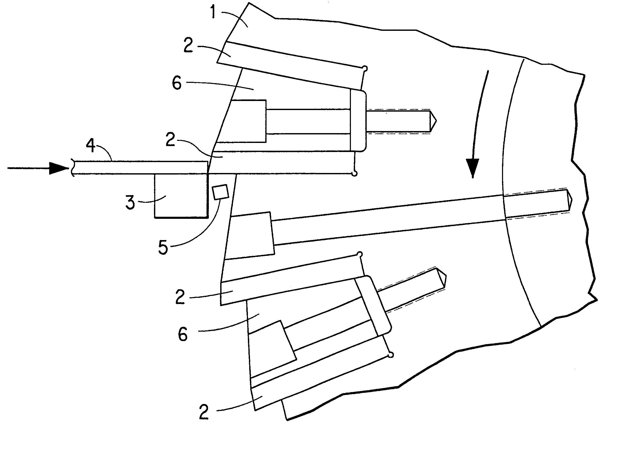
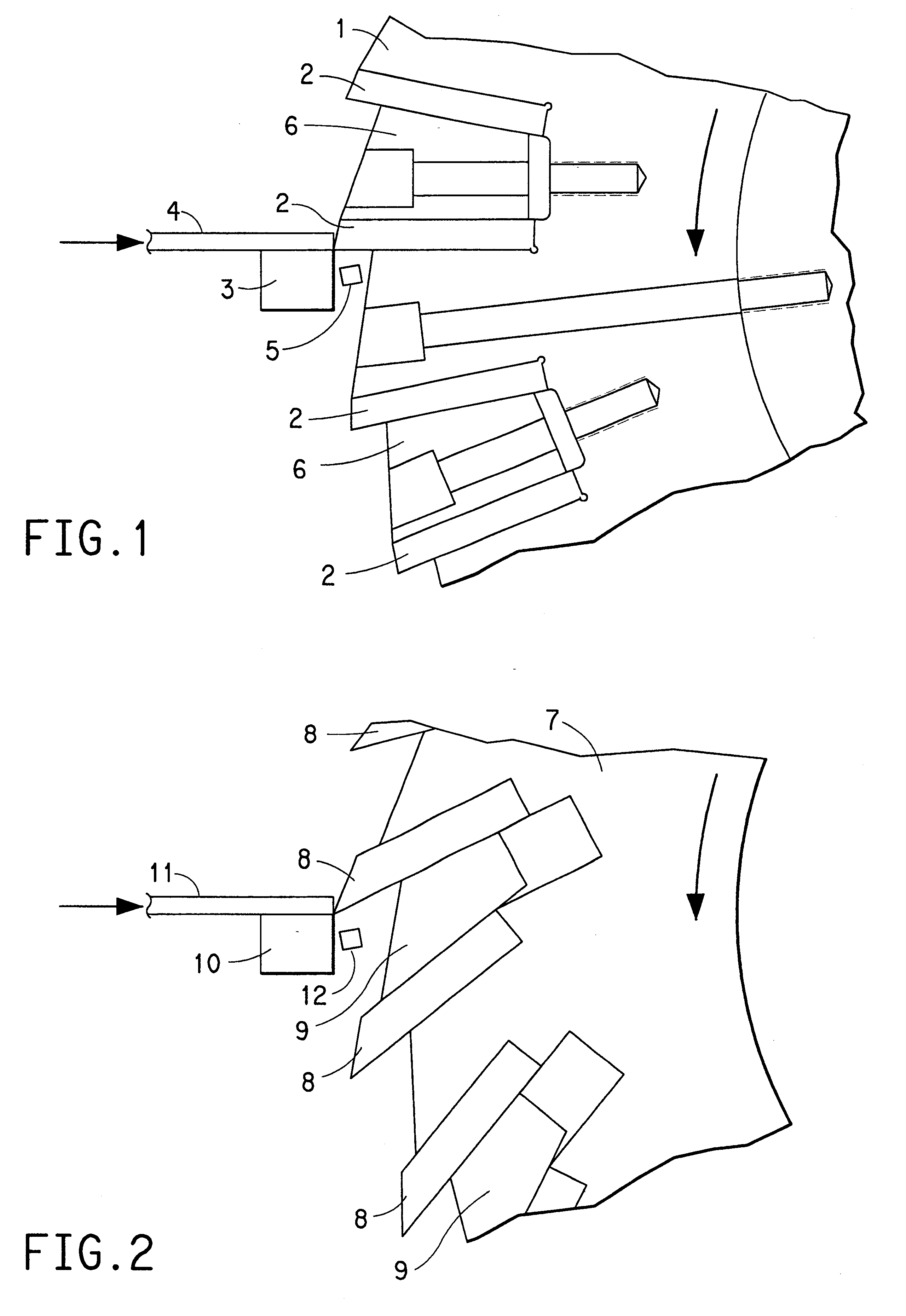
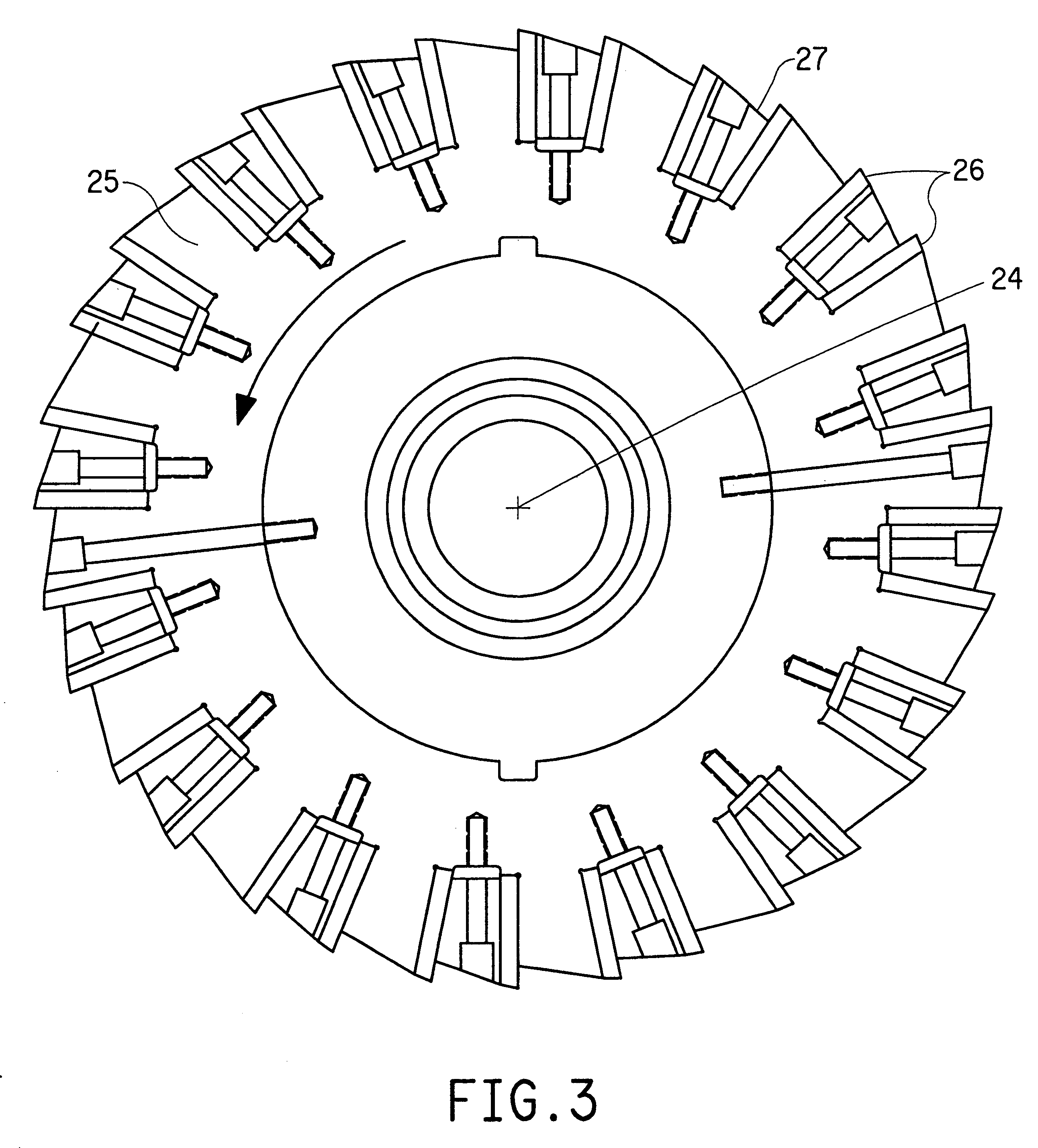
A Model 3508 cutter made by Conair Corp., Bay City, Mich, U.S.A. was used to cut circular cross section polymer strands. The cutter head was used is shown in FIGS. 5 and 6. The diameter of the strands entering the cutter was about 2.3 mm, and the length of the pellet produced was about 2.5 mm. The strands were extruded through die holes about 4.0 to 4.5 mm in diameter and the strands (while molten) were drawn down to about 2.3 mm diameter by the feed mechanism of the cutter. The clearance between the rotor knives and the bed knife was nomially 0.076 mm.

During routine operation, an average of about 545 kg / h of pellets were produced, with the range being about 455 to about 635 kg / h. This entailed feeding 10 to 20 polymer strands at a linear rate of about 60 to about 90 m / min. The maximum rotor speed was 1800 rpm, which was adjusted to produce pellets as described above.

Over a period of about 4 months (about 1,005 actual operating hours) a total of about 450,000 kg of polymer was proce...


PUM

PropertyMeasurementUnit
Angleaaaaaaaaaa
Angleaaaaaaaaaa
Angleaaaaaaaaaa

Abstract

A polymer cutter with a rotary cutting head in which the cutting edges are on the circumferential periphery of the head, and in which the cutting edges shear rather than slice the polymer is described. The knife blades on the rotary head have a cutting edge angle of greater than 70°. The apparatus is especially useful for cutting thermoplastics and may be used for preparing polymer granules or pellets.

Description

This invention concerns a rotary cutting head for cutting polymer, especially polymer strands and the like, and a process for cutting polymer using this head.TECHNICAL BACKGROUNDPolymers are abundant and important items of commerce, being useful in a myriad of applications. During handling, processing or reclamation of polymers it is often necessary to cut the polymers into smaller pieces of various sizes and / or configurations. For instance, when thermoplastics are produced they are often cut into pellets or granules of relatively small size so they can be easily fed to a forming machine such as an injection molding machine or an extruder.Cutters for polymers are available in many forms. In one common form a rotary head containing knives approximately parallel to the axis of rotation is used to cut polymer against a bed knife as the polymer is being fed into the cutter head. Such a cutter is pictured schematically in FIG. 2. In these cutters the knives are such that they cut by a sl...

Claims


Application Information

Patent Timeline
IPC IPC(8): B26D1/01B26D1/38B29B9/06B29B9/02B26D1/00
CPCB26D1/0006B26D1/38B29B9/06B26D2001/0066Y10T83/7876Y10T83/4847Y10T83/9399Y10T83/04
Inventor SAMUELS, MICHAEL ROBERTWAGGONER, MARION GLEN
Owner EI DU PONT DE NEMOURS & CO
Why Eureka
Try Eureka