Method for reducing vibration in a vehicle and a device for accomplishment of the method

a technology for reducing vibration and vehicles, applied in the direction of machines/engines, engine controllers, fuel injection control, etc., can solve the problems of increasing the weight and fuel consumption of the vehicle, and generating vibrations with substantially different frequency components

Inactive Publication Date: 2001-06-19
AB VOLVO
View PDF14 Cites 153 Cited by
  • Summary
  • Abstract
  • Description
  • Claims
  • Application Information

AI Technical Summary

Problems solved by technology

Such a system needs to be fitted with a compressor, which increases the weight and fuel consumption of the vehicle.
This causes the generation of vibrations with substantially different frequency components.

Method used


Image

  • Method for reducing vibration in a vehicle and a device for accomplishment of the method
  • Method for reducing vibration in a vehicle and a device for accomplishment of the method
  • Method for reducing vibration in a vehicle and a device for accomplishment of the method

Examples


Embodiment Construction

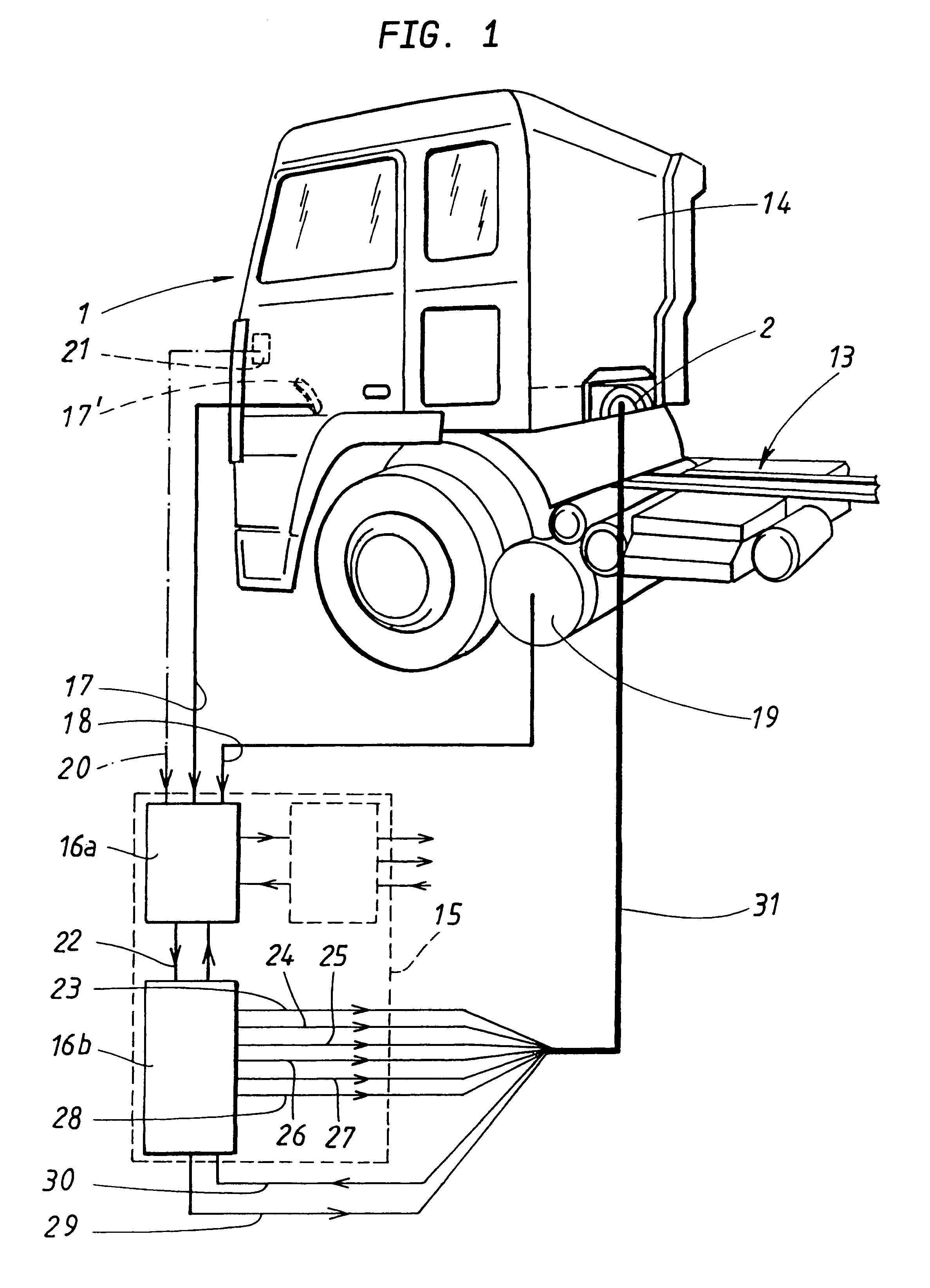
Even during normal operation, a conventional internal combustion engine, for example a piston engine in a motor vehicle, generates a torque which varies with the revolution of the crankshaft. This is due to the fact that each cylinder during one or several, usually two revolutions, goes through different strokes at different angles of the crankshaft for different cylinders, with i.a. a compression stroke which consumes energy and thus affects the crankshaft with a negative torque, and an expansion stroke which supplies power to the piston, and thus causes a positive torque on the crankshaft. When all of the cylinders are in conventional operation, with a smooth supply of fuel to all of the cylinders in a multi-cylinder engine (three or more cylinders), the engine is highly balanced and a minimum of low vibration frequencies are caused. The invention relates to internal combustion engines which are arranged to enable the switching of one or more of the engine cylinders to an alternat...


PUM


Abstract

A method and an arrangement for reducing vibrations in an internal combustion engine (2) which has a plurality of drive units (3-8) connected to a common output shaft (9). These are equipped with a combustion chamber and inlets (34-39) for fuel from organs for fuel supply. Any one of the driving units (7) can be switched from a normal operating condition to an alternative operating condition, in which the supply of fuel to the drive unit is blocked, which causes an alteration in the torque of the driving unit which has been thus switched. The amount of fuel supplied to the drive units which are in a normal operating condition is distributed according to a chosen pattern in order to create torques in these which cause a chosen suppresion of vibrations.

Description

The present invention relates to a method and an arrangement which are intended to be used to suppress vibrations which occur in a vehicle due to imbalances in an engine in the vehicle.TECHNICAL BACKGROUNDThere are a number of vehicles, for example trucks, which have systems which consume, and are driven by, compressed air. In order for these systems to function, access to compressed air is necessary. Access to compressed air is usually achieved by a compressor which compresses air, which is then stored in pressure tanks where it is ready to be used by the compressed air users of the vehicle. The compressor is usually driven by the engine of the vehicle. Such a system needs to be fitted with a compressor, which increases the weight and fuel consumption of the vehicle. In order to make a vehicle financially more attractive, reducing the number of necessary components of the vehicle is of interest.In a piston engine with a plurality of cylinders, in certain operational conditions one ...

Claims


Application Information

Patent Timeline
Patent Type & Authority Patents(United States)
IPC IPC(8): F02D17/02F02D17/00F02D41/02F02D45/00F02D41/04
CPCF02D17/02
Inventor PERSSON, PER
Owner AB VOLVO
Why Eureka
Try Eureka