Fabricating low distortion lap weld construction

a technology of low distortion and lap welds, which is applied in the direction of manufacturing tools, soldering devices, auxillary welding devices, etc., can solve the problems of low strength of lapped joint construction, high distortion, and disadvantageous penetration through penetration

Inactive Publication Date: 2001-06-19
FORD GLOBAL TECH LLC +1
View PDF20 Cites 91 Cited by
  • Summary
  • Abstract
  • Description
  • Claims
  • Application Information

AI Technical Summary

Problems solved by technology

Heretofore, friction stir welding has been used to join members at seams that are not overlapped, due to the anticipated limitation of pin extension that is needed to stir the joint material.
Such through-penetration is disadvantageous because it does not provide for effecti...

Method used


Image

  • Fabricating low distortion lap weld construction
  • Fabricating low distortion lap weld construction
  • Fabricating low distortion lap weld construction

Examples


Embodiment Construction

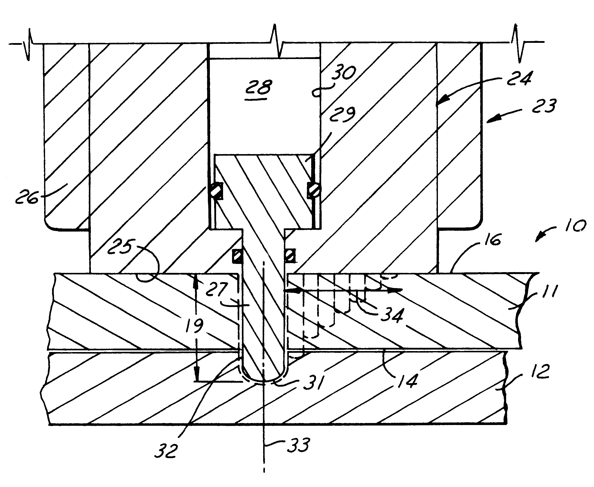
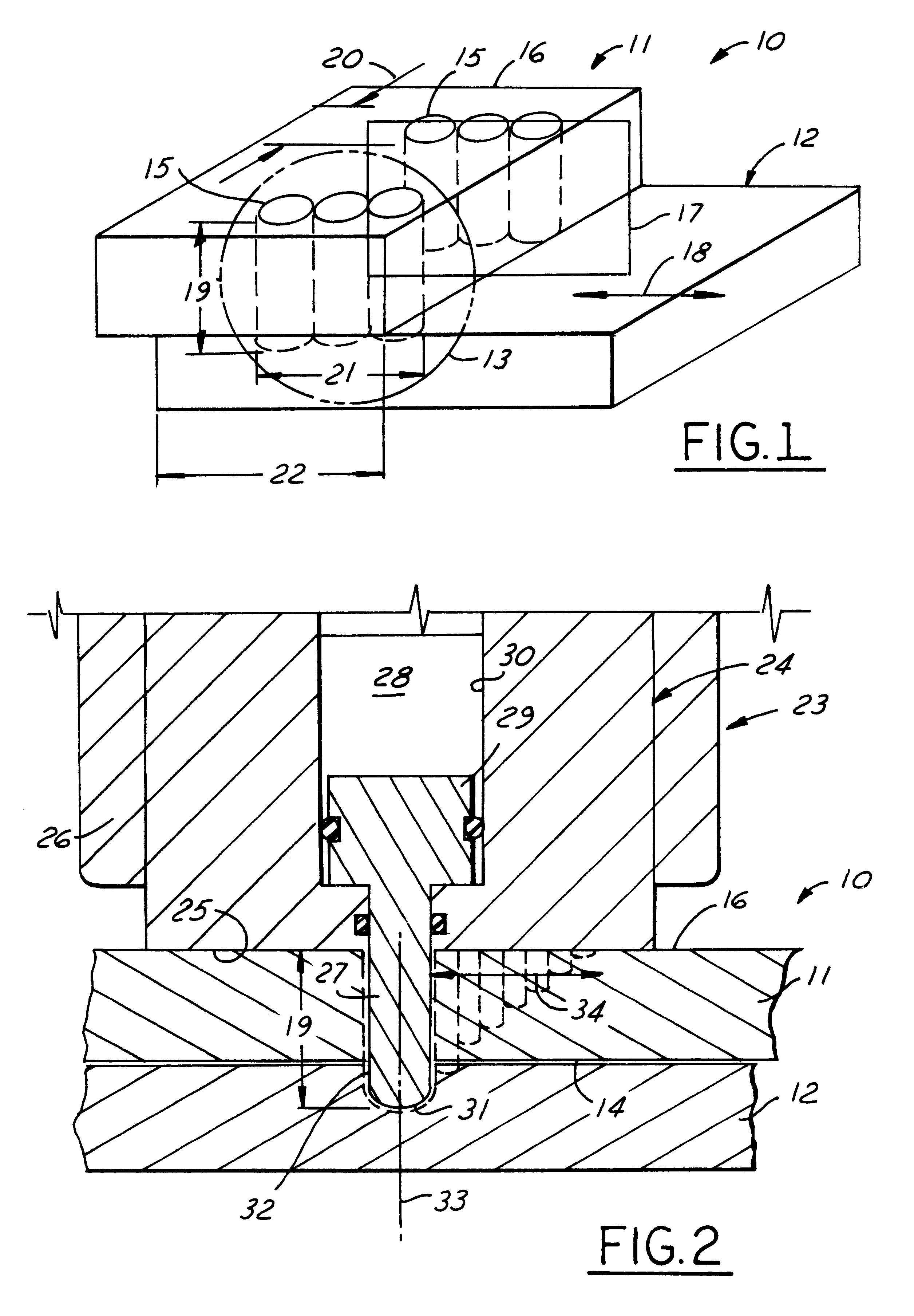
As shown in FIG. 1, a lap joint 10 has been welded by friction stir welding applied in accordance with this invention. The joint 10 comprises a first member 11 and a second member 12 with one sitting on top of the other to define a lapped region 13 and an intercontacting interface 14. The members are comprised advantageously of aluminum but can be any metal that can be converted to a plastic state by friction heating using a relatively small rotating pin. The weld consists of one or more channels 15 of member material that has been friction stirred and extends at least through the interface 14 generally perpendicular to the exposed surface 16 of one of the members. A midplane 17 that extends through the channels is aligned generally to the primary direction 18 of anticipated shear for the joint 10. Channels 15 can have a depth 19 of about 50-75% thickness of member 12 plus the thickness of member 11 (for example, depth 19 may be about 1", a width 20 that corresponds generally to the...


PUM

PropertyMeasurementUnit
Thicknessaaaaaaaaaa
Angleaaaaaaaaaa
Angular velocityaaaaaaaaaa

Abstract

A method of making a low distortion frame construction, the construction having joint regions formed by first and second overlapping members defining a lapped interface, the joint regions being comprised of material that can be converted to a solid state deformable plastic condition by friction heat, comprising: (a) providing a stir friction welding tool having (i) a rotatable thermally conductive body presenting a shoulder to engage the joint region for storing friction-generated heat, and (ii) a friction generating pin rotatable with said body about a pin axis and selectively extendable from the shoulder to progressively penetrate the overlapping members as the joint region in contact with the pin becomes plastic; (b) placing the tool shoulder against the joint region with the pin axis transverse to the lapped interface and spinning the body while progressively extending the pin at a rotational speed effective to generate friction heat that converts the adjacent material of the joint to a plastic condition allowing the spinning of the probe to stir such plastically converted material; and (c) controlling the depth of penetration of the spinning probe while translating the tool across the joint region to perfect a friction stirred welded zone that extends through the interface and between the overlapping members to provide a welded joint that is exceptionally strong in shear.

Description

This invention relates to friction stir welding, and more particularly to a method for creating welded lapped joints using a rotating pin for friction stir welding.DESCRIPTION OF THE PRIOR ARTHeretofore, friction stir welding has been used to join members at seams that are not overlapped, due to the anticipated limitation of pin extension that is needed to stir the joint material. To ensure a sound butt weld, the depth of pin penetration had to be controlled within a very close tolerance, such as within 0.002 inches of the bottom of the faying surface to ensure a sound weld, and the thickness of the joint had to be constant for the weld tool to work properly.In an attempt to extend stir welding to lapped joints, the prior art used through-blade penetration that reciprocatingly cut through both members of a lapped joint leaving a thin line of stirred material which was not strong in shear. Such through-penetration is disadvantageous because it does not provide for effective stirring ...

Claims


Application Information

Patent Timeline
IPC IPC(8): B23K20/12
CPCB23K20/123B23K20/125B23K20/1265B23K2201/06B23K2101/06
Inventor WHITE, DAWN ROBERTAWARD, SUSAN MARIEOROS, ALVIN KENNETH
Owner FORD GLOBAL TECH LLC
Why Eureka
Try Eureka