Plume abated cooling tower

a cooling tower and plume technology, applied in the field of plume abated cooling towers, can solve the problems of high investment, high operating cost, and high construction cost of a specific heat exchanger for dry heating of air, and achieve the effect of reducing the cost of construction, and reducing the cost of operation

Inactive Publication Date: 2001-06-19
HAMON THERMAL EURO
View PDF10 Cites 23 Cited by
  • Summary
  • Abstract
  • Description
  • Claims
  • Application Information

AI Technical Summary

Problems solved by technology

Such known wet-dry cooling towers have many drawbacks, the major of which are the construction of an expensive specific heat exchanger for the dry heating of air, and the consumption of energy for compensating the pressure loss of the water when flowing through the fin tubes of the first heat exchanger.
It means that the investments and the operating costs for such known wet-dry cooling tower are high, whereby industrials are reluctant to use such wet-dry cooling towers.

Method used


Image

  • Plume abated cooling tower
  • Plume abated cooling tower
  • Plume abated cooling tower

Examples


Embodiment Construction

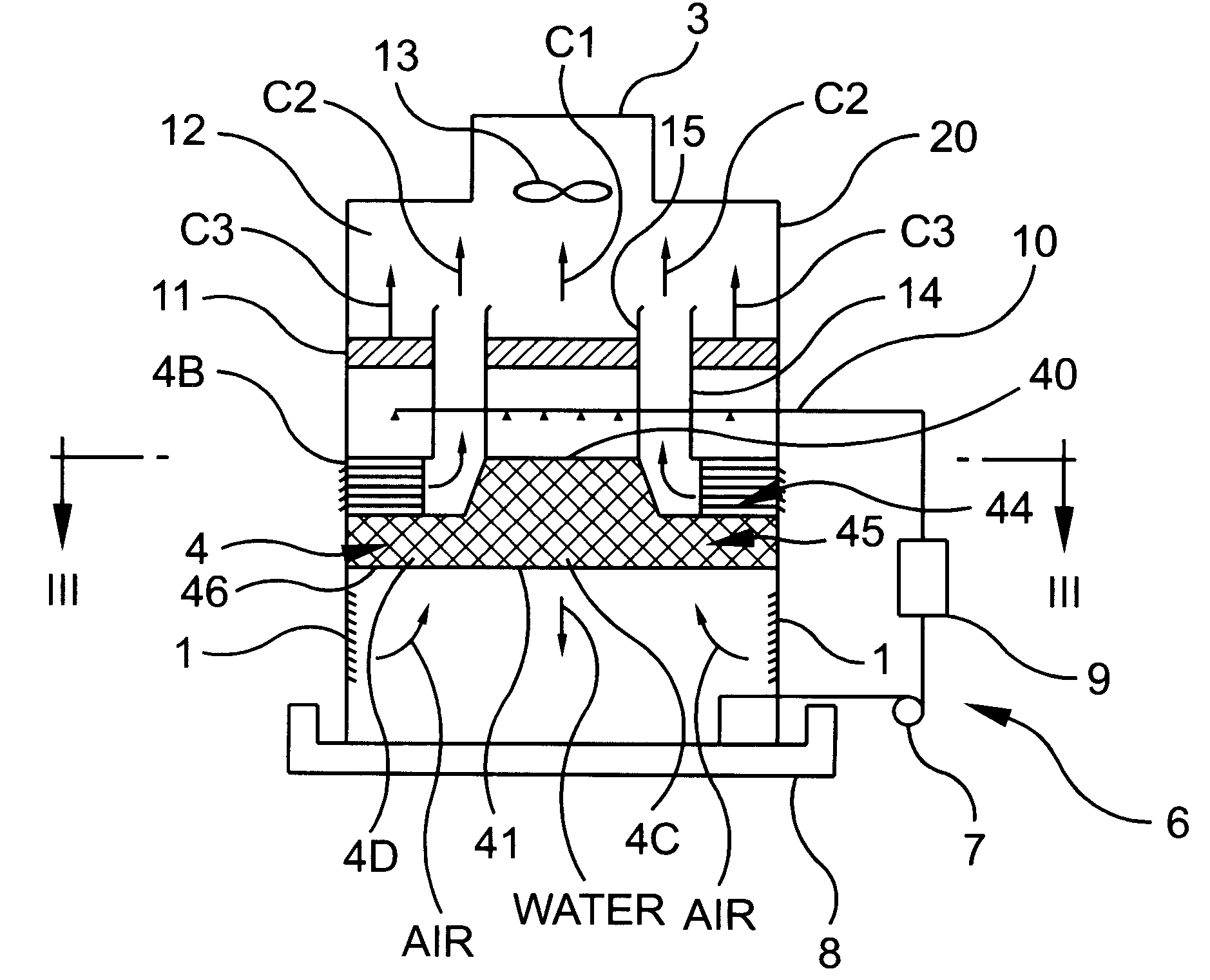
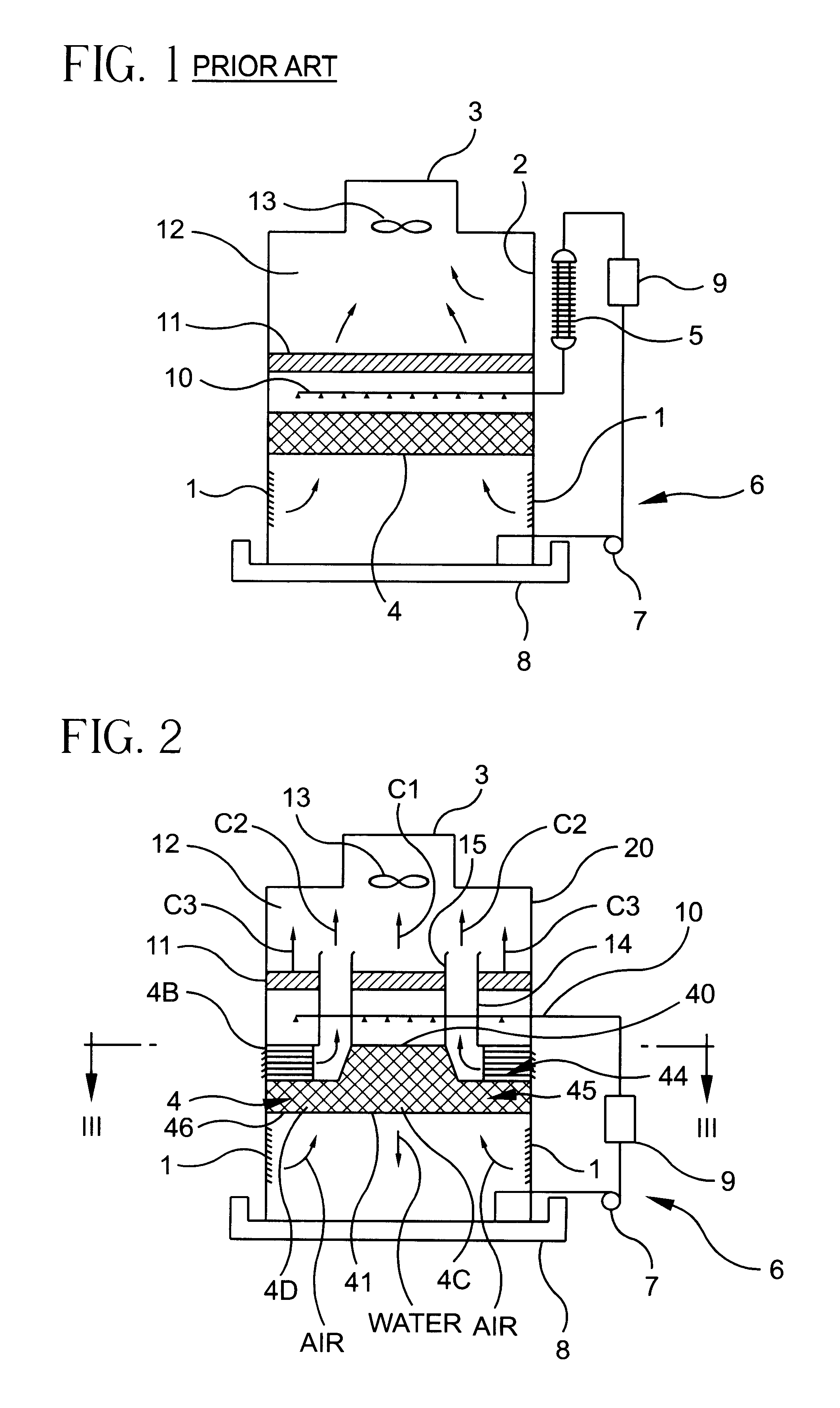
In order to better see the difference and the improvement of a tower according to the invention with respect to a known wet / dry tower, a brief description of a known wet / dry cooling tower will be given hereafter with reference to FIG. 1.

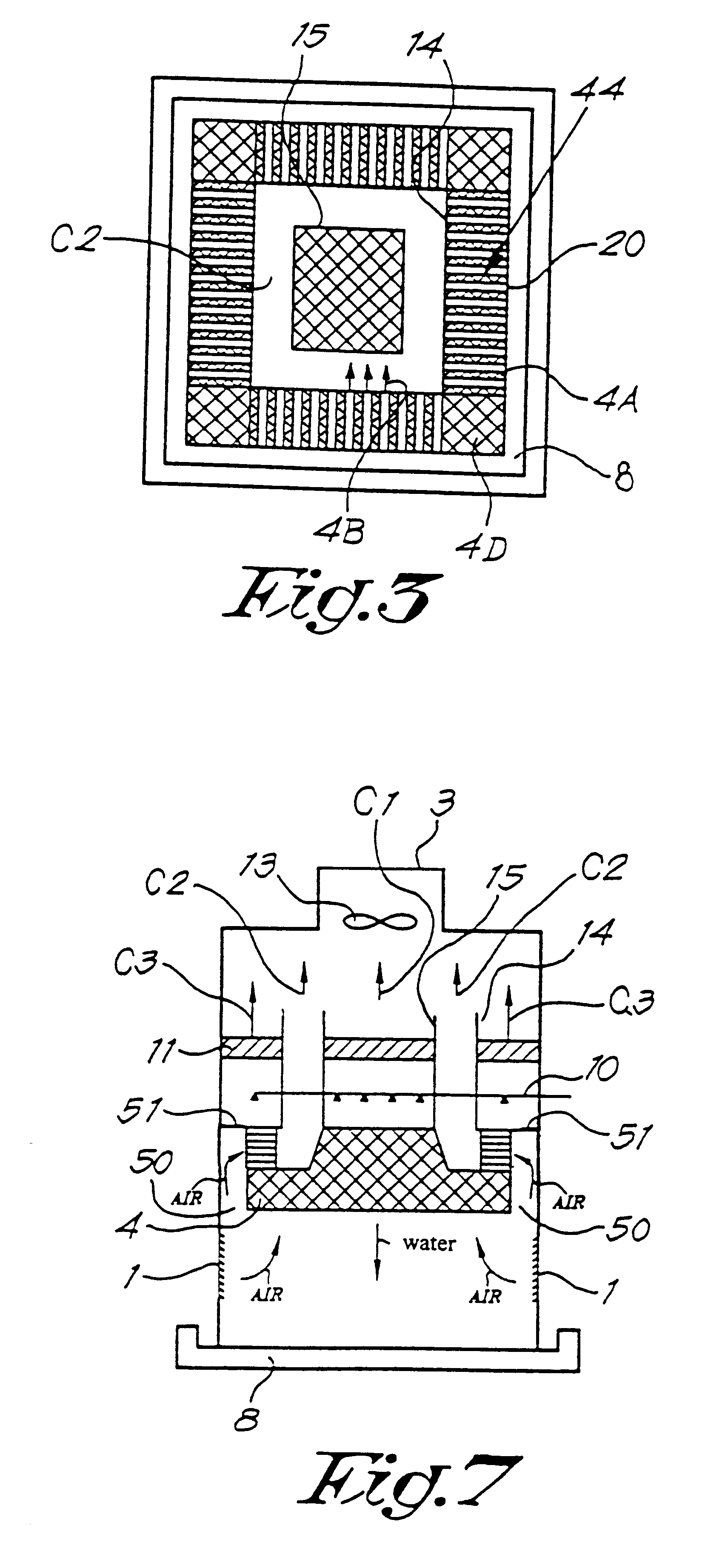
The wet / dry cooling tower of FIG. 1 comprises:

a first air inlet 1 at the bottom of the tower;

a second air inlet 2 in the upper part of the tower;

an air outlet 3;

a fan 13 mounted in the exhaust pipe 3 in order to create by suction air flows between the inlets 1 and 2 and the outlet 3;

a heat exchanger 4 with direct counterflow contact between air and the water to be cooled, said exchanger being located between the inlet 1 and the outlet 3;

an indirect contact heat exchanger 5 with tubes in which water flows, said heat exchanger being mounted in the neighborhood of the inlet 2;

a water flow circuit 6 comprising a pump 7 pumping water from a collecting basin 8 and conveying said water successively in a condensation unit or a process heat exchanger 9 in whi...


PUM


Abstract

The plume abated cooling tower having a heat exchanger in which an aqueous fluid is cooled by an air flow. The heat exchanger has first channels in which air and fluid counterflow, second channels in which air flows, and a means for avoiding the passage of fluid into said second channels, said second channels having a heat conductive surface contacting a plurality of first channels.

Description

THE PRIOR ARTAir cooling towers have been widely used, for example for cooling the water used in a condensation unit of an electrical power plant.Wet cooling towers are towers comprising a heat exchanger on which water is distributed and in which air and the water counterflow. The air escaping the heat exchanger and the tower is charged in water and forms a visible plume, which is an esthetical pollution. In certain instances, the formation of plume has even to be completely avoided for example when the cooling tower is located near a road or in a city.In order to solve the problem of plume, various wet-dry type cooling towers have been proposed.Said wet-dry cooling towers comprises two distinct heat exchangers, namely a first indirect contact heat exchanger for the dry heating of a first air flow, said first heat exchanger having fin tubes in which the water coming from the condensation unit flows, before being sprayed onto a second direct contact heat exchanger having channels in ...

Claims


Application Information

Patent Timeline
Patent Type & Authority Patents(United States)
IPC IPC(8): F28C1/14F28C1/00
CPCF28C1/14Y10S261/77Y10S165/90Y02B30/70
Inventor VOUCHE, MICHEL
Owner HAMON THERMAL EURO
Why Eureka
Try Eureka