Apparatus and method for minimizing electromagnetic interference in microcomputing systems

a microprocessor and electromagnetic interference technology, applied in the field of microcomputing, can solve the problems of increasing processing speed, emi is a speed limiting factor in the microprocessor, and the emission of electromagnetic interference (emi) from the microprocessor

Inactive Publication Date: 2001-06-26
INTEL CORP
View PDF5 Cites 28 Cited by
  • Summary
  • Abstract
  • Description
  • Claims
  • Application Information

AI Technical Summary

Problems solved by technology

One of the major limitations when attempting to increase processing speed is the emission of electromagnetic interference (EMI) from the microprocessors employed in such microcomputing systems.
EMI is a speed limiting factor in microcomputing systems because it has a tendency to create unwanted high-frequency current loops in the motherboard of the microcomputing system.
More specifically, the unwanted current loops on the motherboard emit high-frequency EMI known to interfere with the communications frequencies regulated by the Federal Communications Commission (FCC).
However, this special trace routing is disadvantageous in that it consumes a fair amount of space on the motherboard, which, as will be appreciated, cuts against ...

Method used


Image

  • Apparatus and method for minimizing electromagnetic interference in microcomputing systems
  • Apparatus and method for minimizing electromagnetic interference in microcomputing systems
  • Apparatus and method for minimizing electromagnetic interference in microcomputing systems

Examples


Embodiment Construction

Illustrative embodiments of the invention are described below. In the interest of clarity, not all features of an actual implementation are described in this specification. It will of course be appreciated that in the development of any such actual embodiment, numerous implementation-specific decisions must be made to achieve the developers' specific goals, such as compliance with system-related and business-related constraints, which will vary from one implementation to another. Moreover, it will be appreciated that such a development effort might be complex and time-consuming, but would nevertheless be a routine undertaking for those of ordinary skill in the art having the benefit of this disclosure.

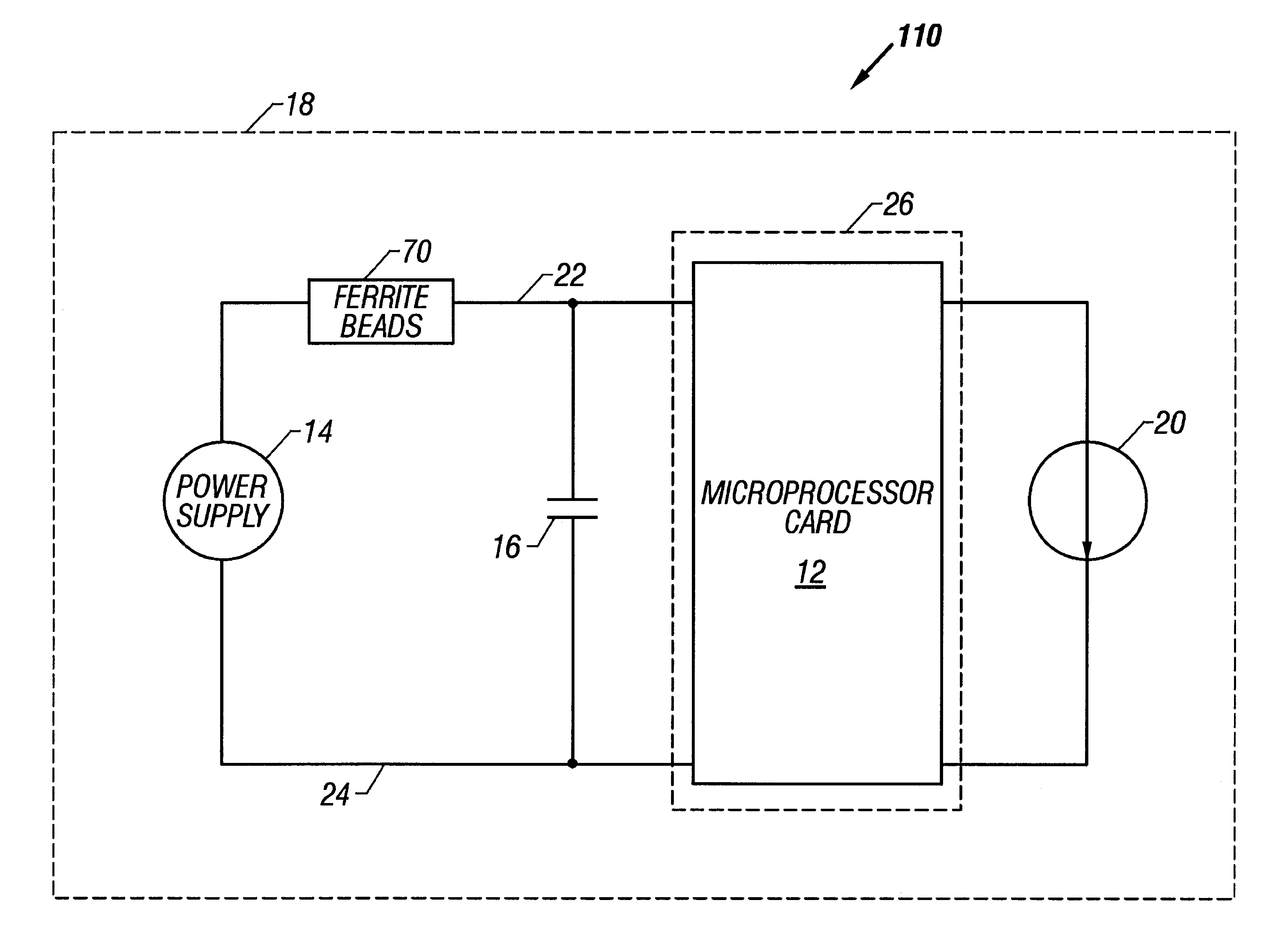
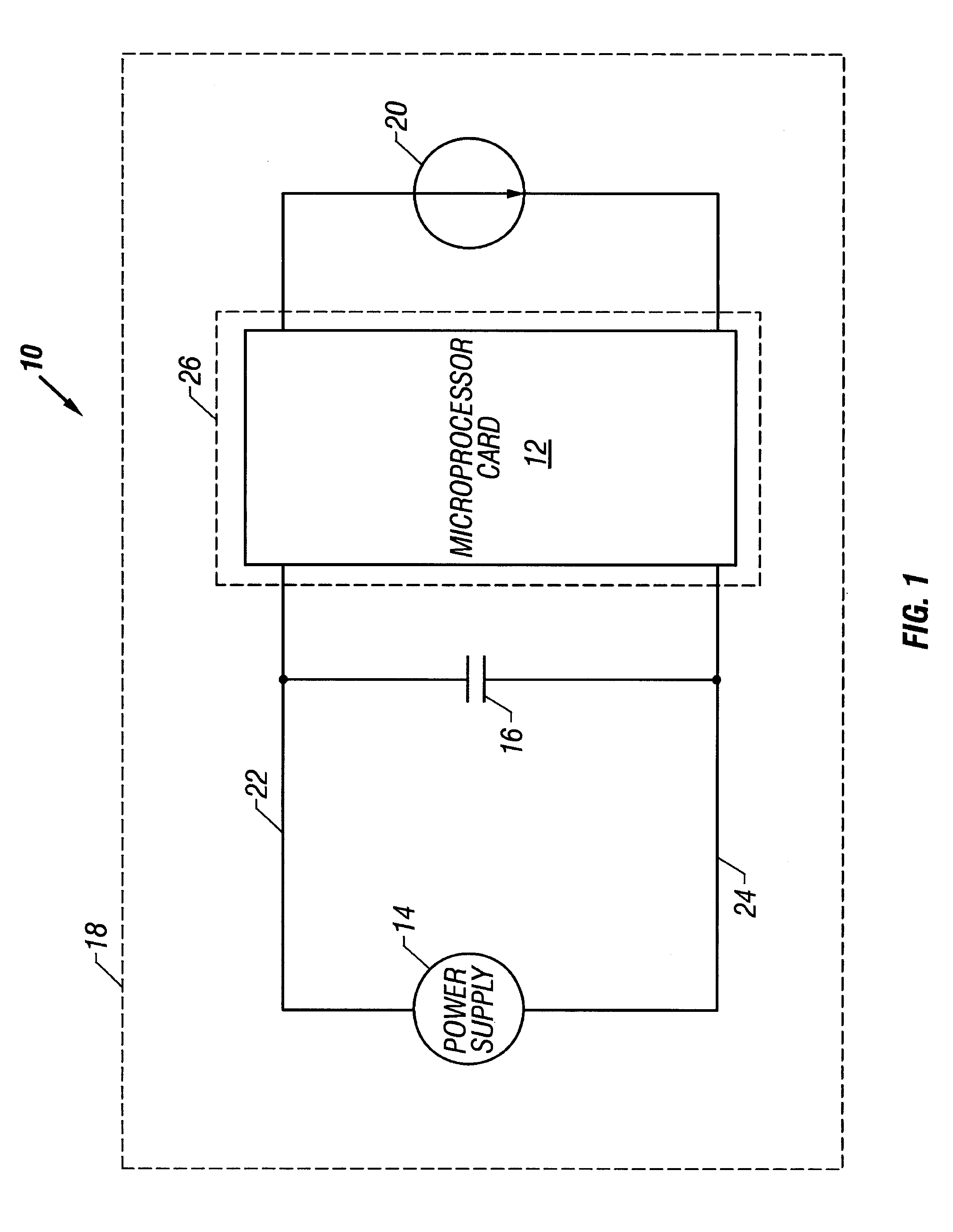
With initial reference to FIG. 1, shown is a microcomputing system 10 incorporating an apparatus and method for reducing EMI in accordance with one embodiment of the present invention. In its most generic form, the microcomputing system 10 includes a microprocessor card 12, a power sup...


PUM


Abstract

An apparatus and method for minimizing electromagnetic interference in a microcomputing system. The apparatus and method of the present invention are based on the fundamental aspect of providing an EMI shield specifically dimensioned to receive a microprocessor within the microcomputing system. The apparatus and method of the present invention are further based on the aspect of providing at least one ferrite bead along a power delivery path to attenuate any high-frequency leakage current from the microprocessor that results at the resonant frequencies of the EMI shield.

Description

1. Field of the InventionThe present invention relates generally to the field of microcomputing, and, more particularly, to an apparatus and method for minimizing electromagnetic interference in microcomputing systems.2. Description of the Related ArtIn the field of microcomputing, an increasingly high premium is placed on maximizing processing speed. One of the major limitations when attempting to increase processing speed is the emission of electromagnetic interference (EMI) from the microprocessors employed in such microcomputing systems. EMI is a speed limiting factor in microcomputing systems because it has a tendency to create unwanted high-frequency current loops in the motherboard of the microcomputing system. More specifically, the unwanted current loops on the motherboard emit high-frequency EMI known to interfere with the communications frequencies regulated by the Federal Communications Commission (FCC). To avoid running afoul of FCC regulations against interfering with ...

Claims


Application Information

Patent Timeline
IPC IPC(8): H04B15/00H04B15/02
CPCH04B15/005H04B15/02
Inventor ZHANG, MICHAEL T.WEISS, DONWEBB, JAMESLOFLAND, STEVE
Owner INTEL CORP
Why Eureka
Try Eureka