Enhanced minimum tillage planter/renovator system

a planter/renovator and minimum tillage technology, applied in the direction of agricultural machines, agricultural gas emission reduction, agricultural tools and machines, etc., can solve the problems of sod to explode outward and roll, require far too much weight for slicing coulters, and provide an inefficient and sometimes difficult means of establishing leading slices, etc., to improve the seed bed and clean furrow, and improve the efficiency of the planter/renovator. performance, the effect of cost-competi

Inactive Publication Date: 2001-07-10
TARVER III SAM A
View PDF4 Cites 6 Cited by
  • Summary
  • Abstract
  • Description
  • Claims
  • Application Information

AI Technical Summary

Benefits of technology

Unlike the prior art, the present invention contemplates a minimum tillage planter/renovator system which provides an enhanced seed bed and clean furrow, with nominal ground cover disturbance, in a variety of soil conditions. Thus,

Problems solved by technology

However, when conventional minimum tillage planters are utilized with soft or spongy ground, the furrow and seedbed is formed, only to have it shrink , with the furrow providing little open area on the ground cover for sunlight and passage of the seedlings therethrough.
A general problem with this prior art arrangement is that the leading slicing coulter requires far too much weight to penetrate hard ground, providing an inefficient and sometimes difficult means of establishing a leading slice.
The consequence of this is that the sod/roots move back into near condition leaving a too narrow seed bed and furrow to allow suffici

Method used


Image

  • Enhanced minimum tillage planter/renovator system
  • Enhanced minimum tillage planter/renovator system
  • Enhanced minimum tillage planter/renovator system

Examples


Embodiment Construction

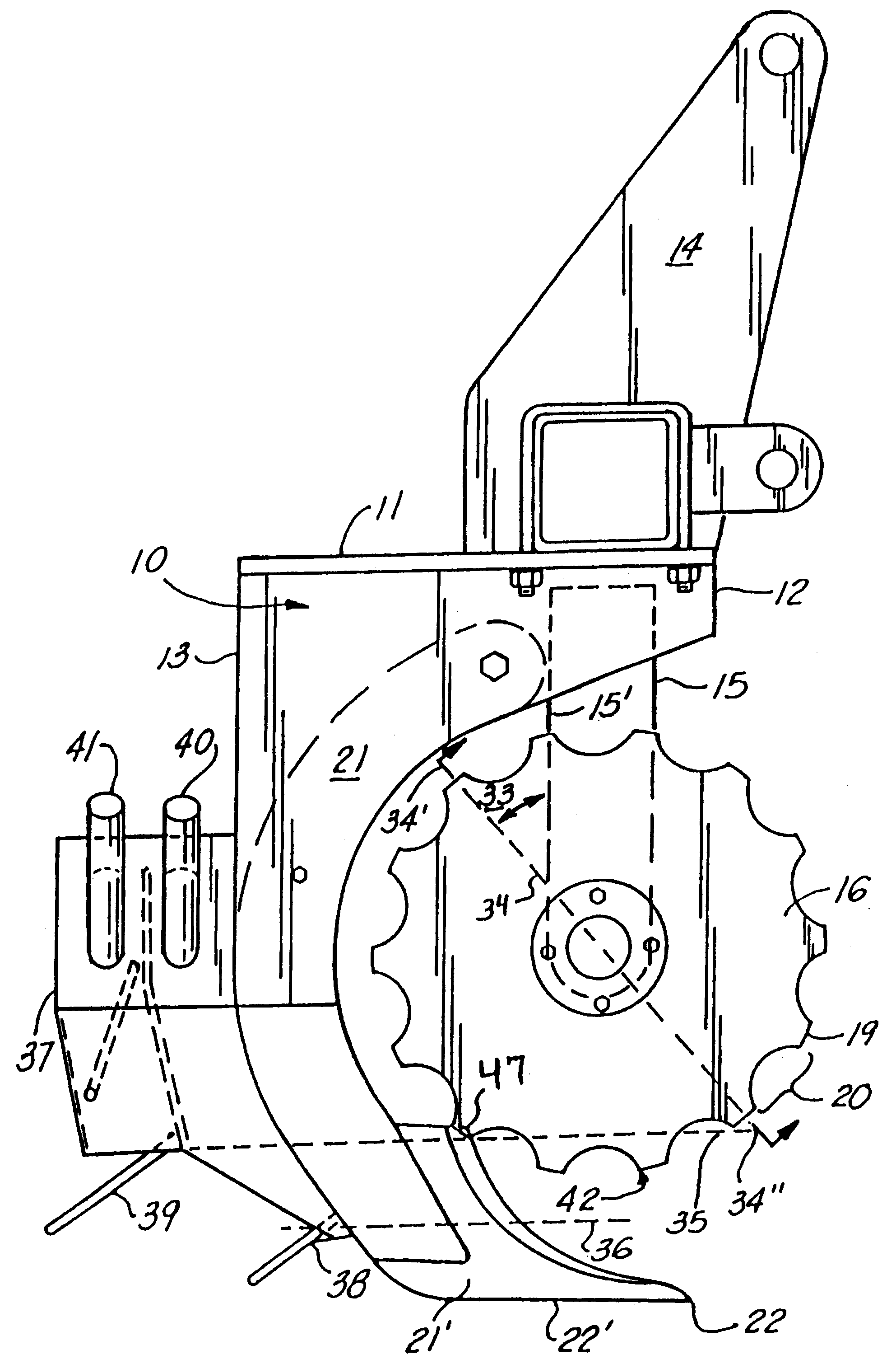
A new, preferred embodiment of the invention is disclosed in FIGS. 5A-5F, particularly FIG. 5E, comprising a frame 111 having a first, frontal end 112 and a second, rear end 113. The unit may be motivated via a standard, three point hitch, which may be utilized by a tractor or other implement to motivate the present system, as shown in the discussion of the first embodiment of the invention.

Continuing with the drawings, emanating from the frame 111 in the vicinity of the first end 112 in angled fashion pivotal support member 115, configured to support first 116 and second 117 coulter discs about said support member, via respective axles 118 in angled relationship, as will be further discussed infra. As shown, the outer diameter 119 of the coulter discs 116, 117 may be rippled 120, as better illustrated in FIG. 5C. This rippled outer diameter has been found to provide enhanced grinding and processing action of the organic matter and soil displaced by the footshank, when compared to t...


PUM


Abstract

A minimum tillage planting/renovation system configured to facilitate an enhanced seedbed in a variety of soil conditions, while maintaining nominal surface disturbance. The present invention may further be configured to provide intercrop planting, renovating, and/or fertilizing. The system of the present invention contemplates a planter/fertilizer wherein there is provided a ripping point configured to penetrate a predetermined depth into the soil or sod, the ripping point designed to facilitate a splitting and lifting of the soil, forming a seed bed void, while cutting any organic ground cover, which might comprise, for example, sod, widening the ground cover, and lifting same to a prominent head, wherein first and second coulters, situated above and about the ripping point, are configured to independently engage and cut first and second sides of the lifted ground cover, trash and the like, respectively, then cutting the lifted ground cover, etc., as the coulters rotate, the coulters cooperatively grinding at least a portion of the lifted ground cover, forming tilth, and redepositing the tilth into the seedbed void, providing an enhanced seedbed region with nominal surface disturbance, and a clean furrow.

Description

This invention relates to a cultivation equipment and methods, and in particular to a minimum tillage planting / renovation system configured to facilitate an enhanced seedbed in a variety of soil conditions, while maintaining nominal surface disturbance. The present invention may further be configured to provide intercrop planting, renovating, and / or fertilizing.The system of the present invention contemplates a planter / fertilizer wherein there is provided a ripping point configured to penetrate a predetermined depth into the soil or sod, the ripping point designed to facilitate a splitting and lifting of the soil, forming a seed bed void, while cutting any organic ground cover, which might comprise, for example, sod, widening the ground cover, and lifting same to a prominent head, wherein first and second coulters, situated above and about said ripping point, are configured to independently engage and cut first and second sides of the lifted ground cover, trash and the like, respect...

Claims


Application Information

Patent Timeline
IPC IPC(8): A01B49/00A01B49/06A01C7/00
CPCA01C7/006A01B49/06Y02P60/20Y02A40/22
Inventor TARVER, III, SAM A.
Owner TARVER III SAM A
Why Eureka
Try Eureka