
Virtual tape system with variable size

a tape system and variable size technology, applied in the field of storage devices, can solve the problems of degrading the host performance of other applications, data stored in the tape may only occupy a few percent of the available storage space in the tape, and the tape utilization is often poor

Inactive Publication Date: 2001-07-10
EMC IP HLDG CO LLC
View PDF9 Cites 101 Cited by
  • Summary
  • Abstract
  • Description
  • Claims
  • Application Information

AI Technical Summary

Problems solved by technology

Unfortunately as a particular batch job must make a transfer to one tape, tape utilization often times is poor.
That is, the data stored in a tape may occupy only a few percent of the available storage space in the tape.
Moreover associated testing and transfer operations require host processing cycles that can degrade host performance for other applications.
Although the process can improve performance somewhat, tape utilization still is generally poor.
When such under utilization occurs, the real cost for tape becomes significantly higher.
That is, the total cost of the media associated with the under utilized tape increases the "per-byte" cost of actual storage.
The alternative is to add more tape drives, but that increases the floor space required for the data center.
Buffer capacity in such systems is limited.
This recycling process is extremely time consuming especially in data processing systems with hundreds or thousands of magnetic tapes.
Consequently the total costs for storing data on magnetic tape storage devices can be significantly higher than the perceived cost.
Simultaneously with the increased need for tape storage, the cost of storage on magnetic disk storage devices is falling.
However, such proposals require new special-purpose hardware and software modifications such that emulation is not transparent to the user.
Consequently the emulation does not act as a true virtual device.
However, as these applications undergo program continuing development, programming errors can appear.
In some situations this could involve filling multiple tape cartridges with useless data.
While such data is easy to delete from a magnetic disk storage device, a primary problem lies in the resources that must be devoted to processing such an endless loop, particularly any common cache that is involved when an endless loop is processed.
Such an allocation of resources will be to the detriment of other application programs that are running concurrently in a multi-processor system.

Method used


Image

  • Virtual tape system with variable size
  • Virtual tape system with variable size
  • Virtual tape system with variable size

Examples


Embodiment Construction

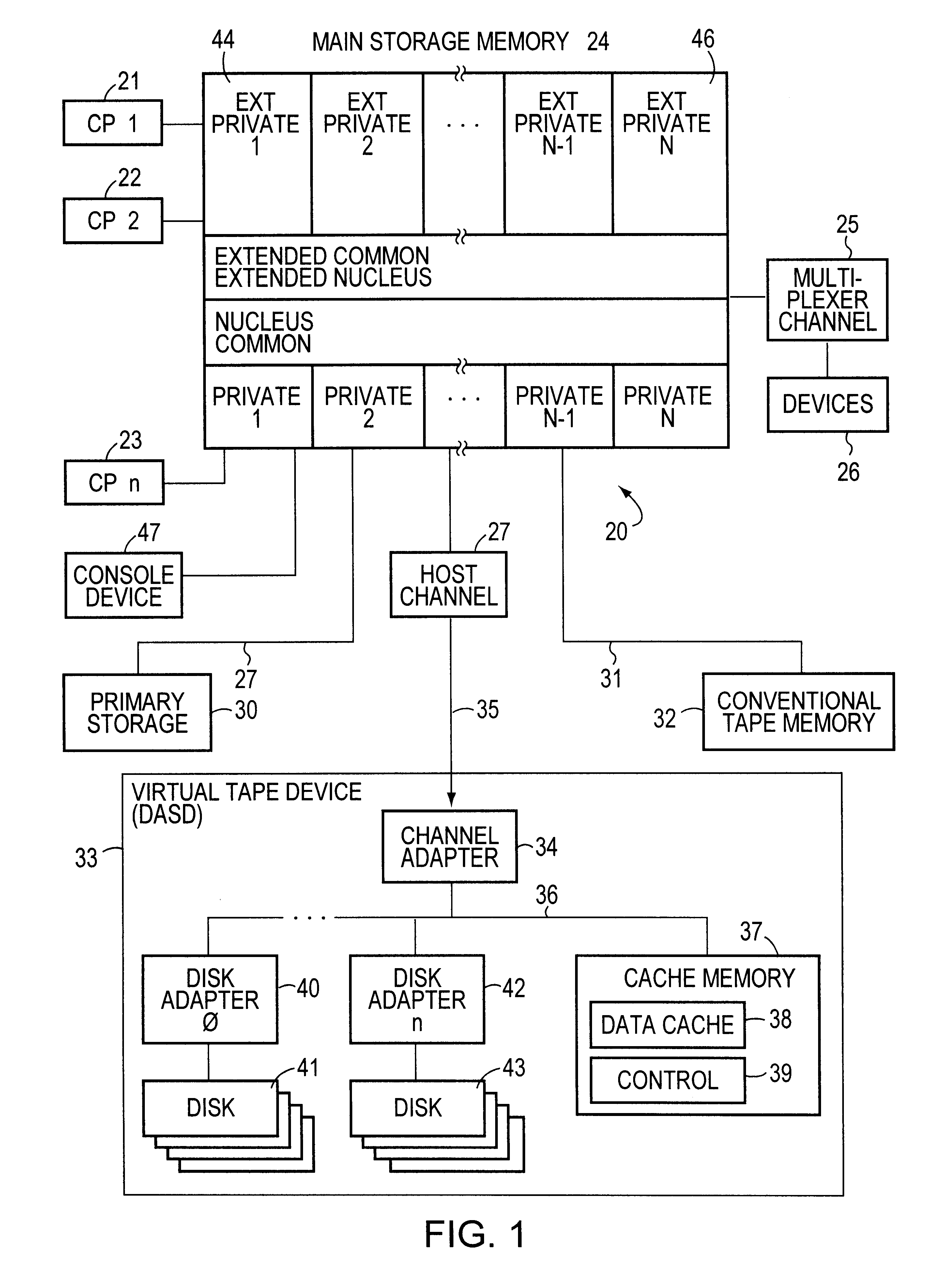
FIG. 1 depicts a data processing system 20 which, for purposes of explaining this invention, is shown as an IBM based system. The system 20 comprises multiple central processors (CP) identified as CP1-21, CP2-22 and CPn-23 where n is the maximum number of central processors that comprise the data processing system 20. Each central processor connects to a main storage unit 24. In an IBM MVS environment the main storage unit 24 is divided into a number of sections that, as known, include private, common, nucleus, extended nucleus, extended common and extended private storage areas.

A channel 25 provides a communications path for devices 26 such as printers, local terminals and the like. Another channel 27 establishes a communications path to a primary storage unit, such as a magnetic disk storage unit. Still another channel 31 establishes a communications path with a conventional tape storage system 32. Such systems and their operations, including the methods by which data is exchanged...


PUM


Abstract

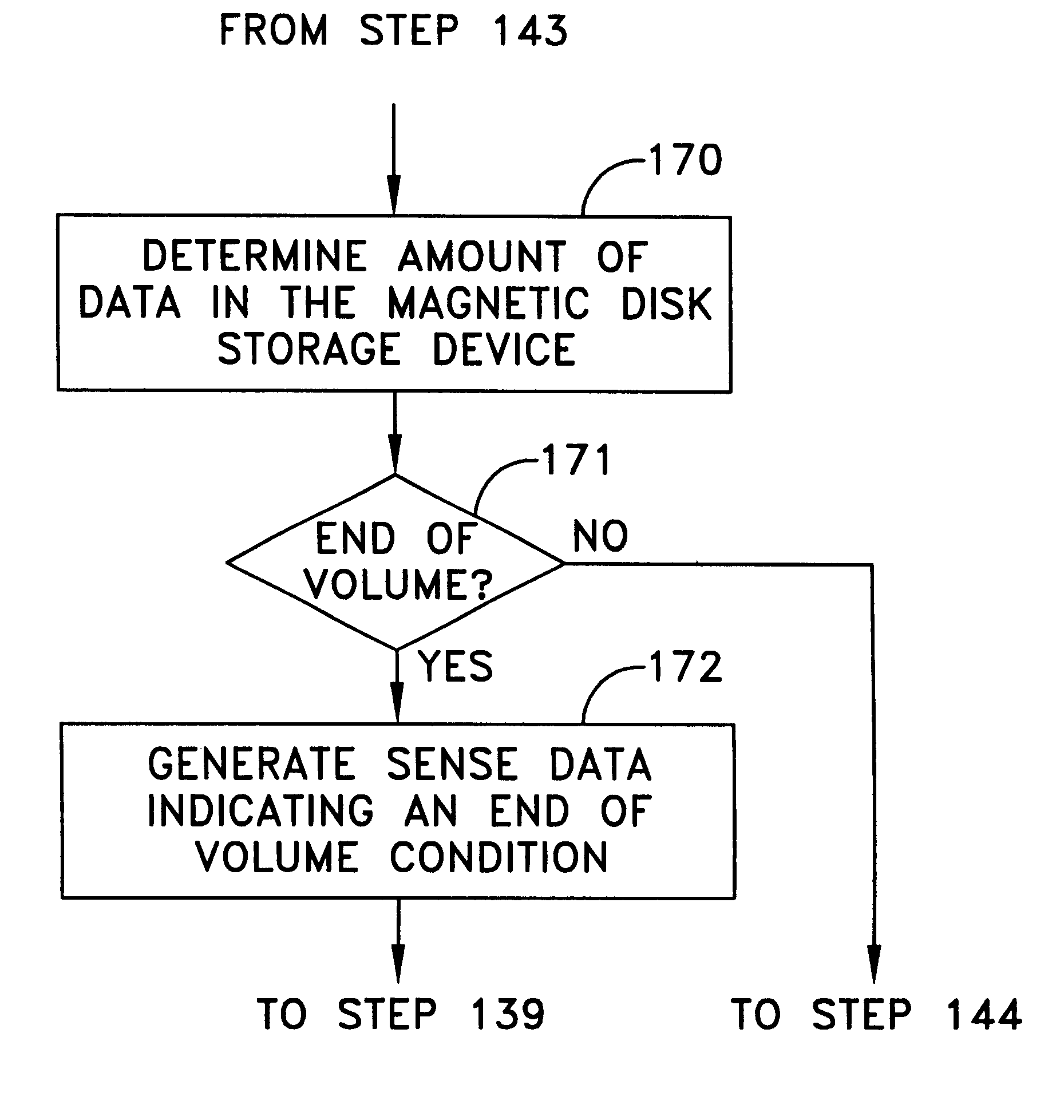
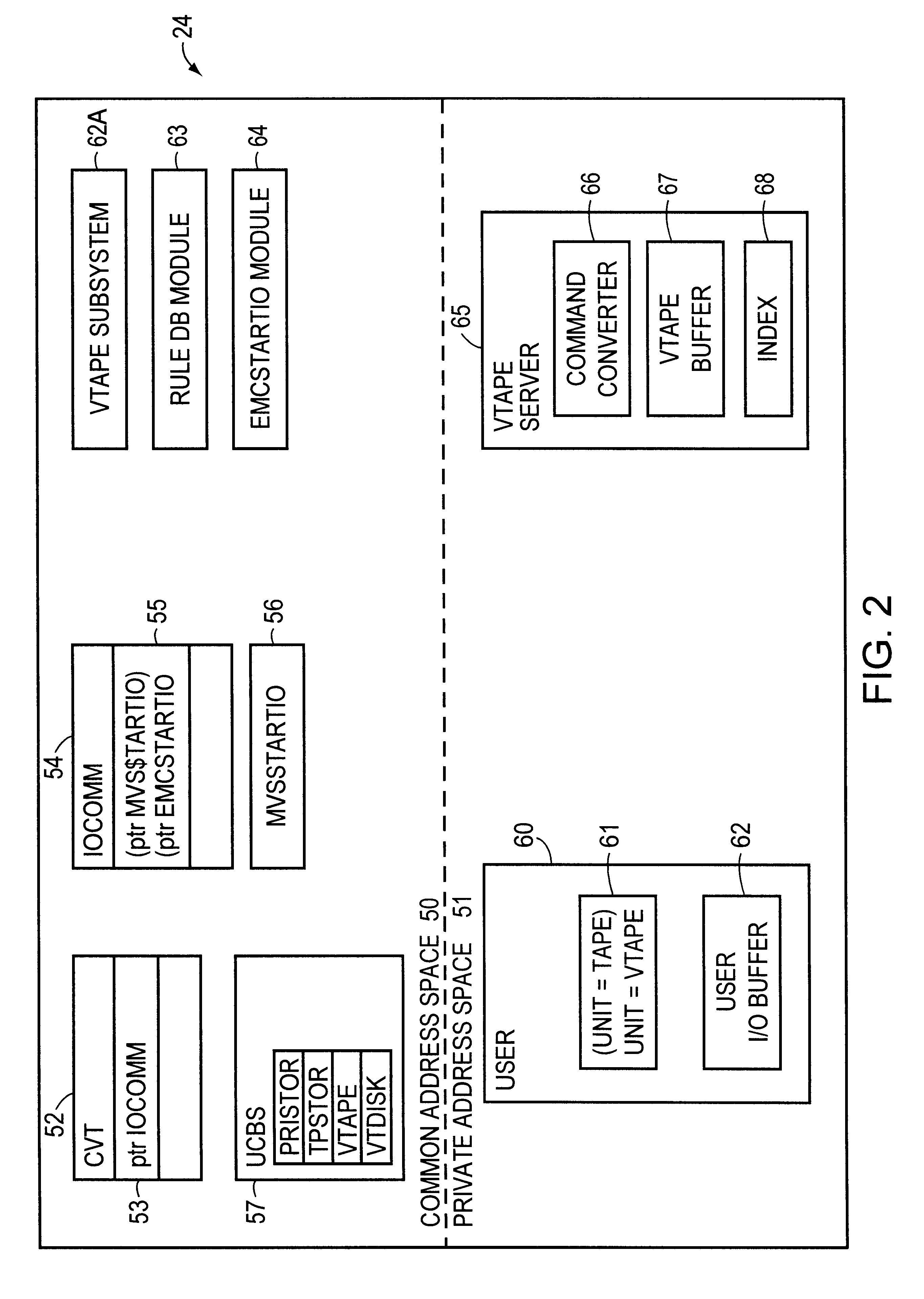
A method and apparatus for emulating a magnetic tape storage device with a conventional, unmodified magnetic disk storage device. I / O output requests for the emulated magnetic tape storage device are intercepted to determine whether they involve a virtual tape resource that comprises a magnetic disk storage device. Tape requests to such a resource are converted into one or more conventional magnetic disk storage requests to effect an analogous operation. The size of the virtual tape resource can be reduced below the normal data capacity for the emulated tape storage device.

Description

1. Field of the InventionThis invention generally relates to storage devices for use in data processing systems and more particularly to a system that enables a magnetic disk storage device to emulate a magnetic tape storage device.2. Description of Related ArtData centers that process and maintain large quantities of data generally include two types of mass storage devices, namely: magnetic disk storage devices and magnetic tape storage devices. Both types of mass storage devices typically operate in large-scale, multiple-processor systems. These systems further include sophisticated operating systems for controlling various resources connected to one or more central processors. The Multiple Virtual System of IBM (commonly called "MVS") is one such system.Data centers operate with different configurations that may include certain magnetic disk storage devices organized as primary storage devices. Other magnetic disk storage devices may act as mirrors or may act as redundant storage...

Claims


Application Information

Patent Timeline
IPC IPC(8): G06F9/455G06F3/06
CPCG06F3/0607G06F9/455G06F3/0676G06F3/0664
Inventor LECRONE, DOUGLAS E.HASS, YESHAYAHUCOHEN, ELCANA
Owner EMC IP HLDG CO LLC
Learn More