
Mast mounting system and method

Inactive Publication Date: 2001-07-17
TIM PRICE INC
View PDF6 Cites 20 Cited by
  • Summary
  • Abstract
  • Description
  • Claims
  • Application Information

AI Technical Summary

Benefits of technology

Accordingly, it is the principal object of the present invention to provide an improved mast mounting system for vehicles and shelters.
A still further object of the invention is that, following deployment and separation of the vehicle from the mast, it shall be possible with a two person crew to safely, efficiently and expeditiously restore the mast to the transport condition on the vehicle. In addition, it shall be an objective of the invention that it shall be possible for a one person crew to safely carry out the restoration operation.

Problems solved by technology

Combined weight of mast and payload can easily exceed three hundred pounds, generating very large moments which can be hazardous if not managed with care.

Method used


Image

  • Mast mounting system and method
  • Mast mounting system and method
  • Mast mounting system and method

Examples


Embodiment Construction

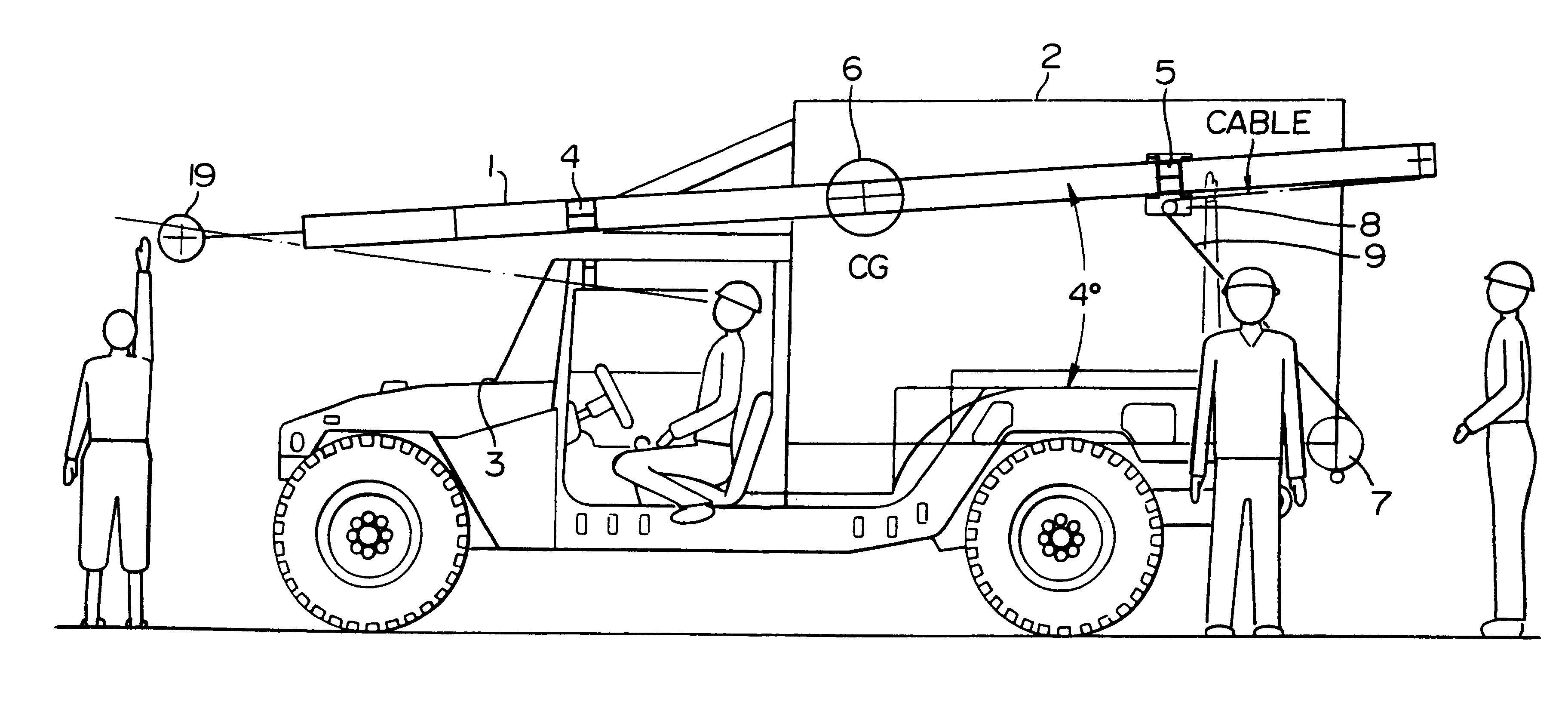
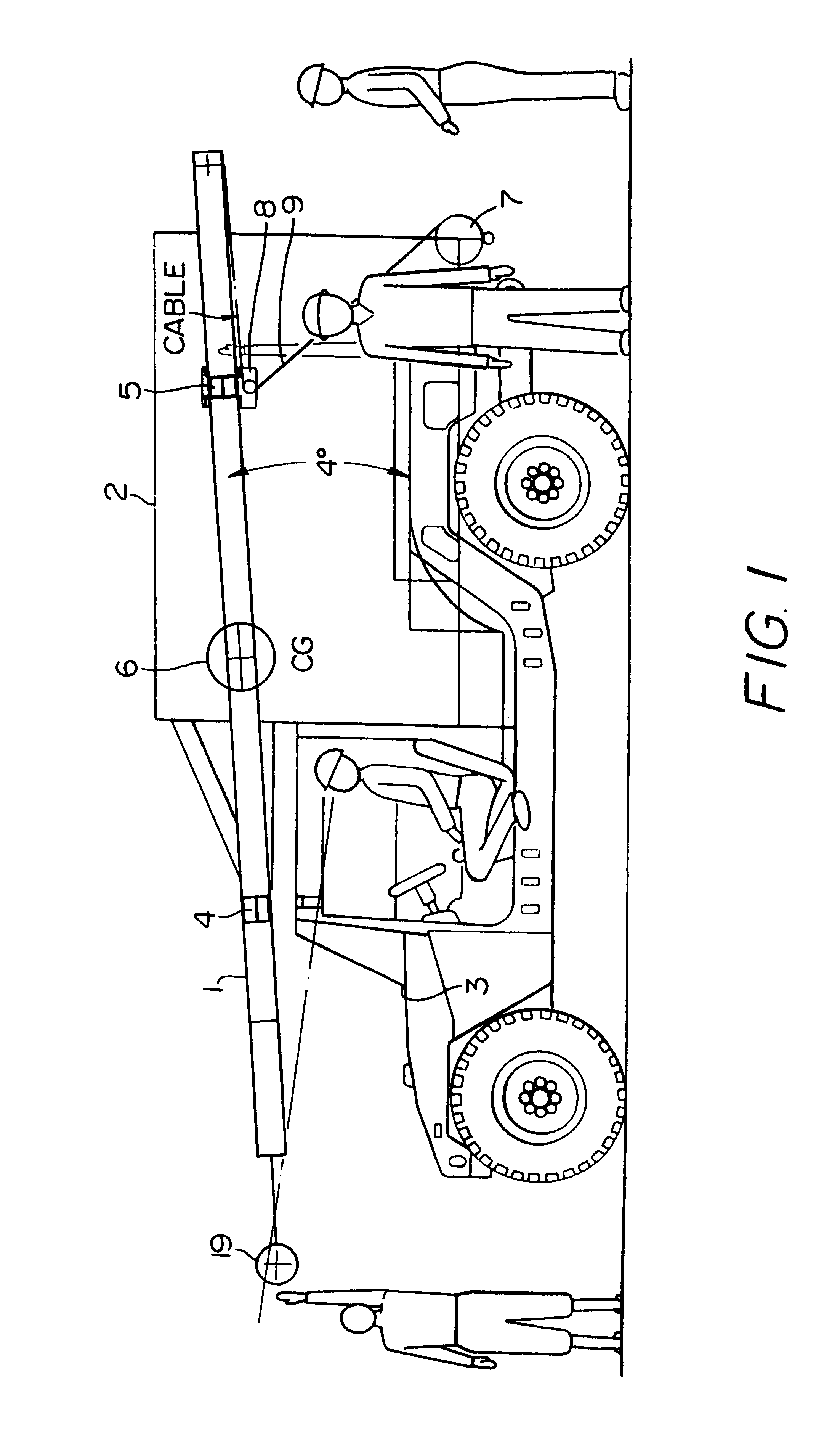
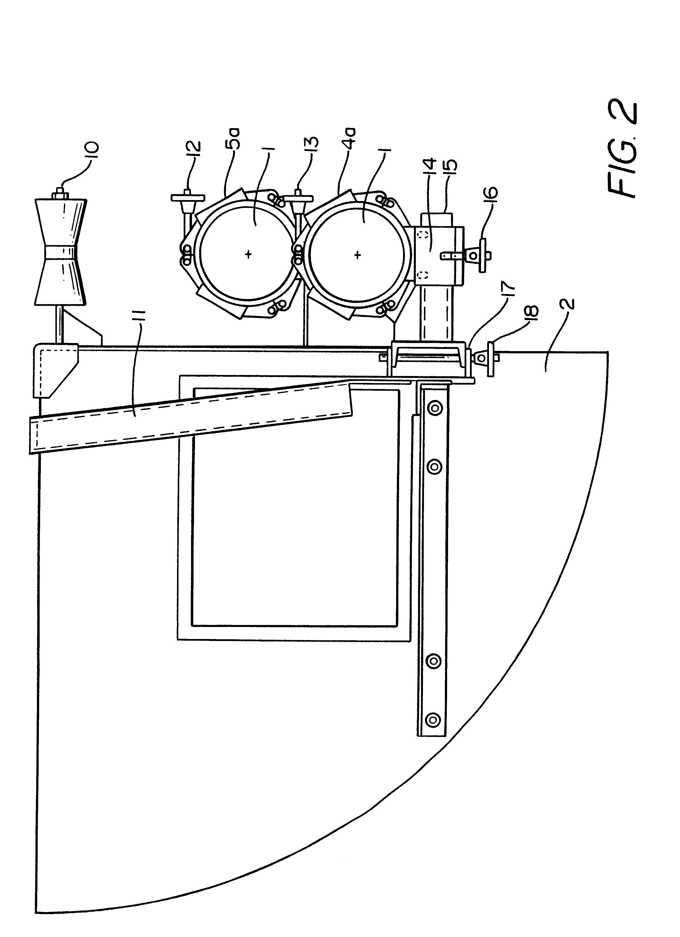
Briefly, in accordance with the invention, we provide an integrated mast mounting system for vehicles and shelters which utilizes at least two clamp bracket assemblies. The clamp bracket assemblies are mounted to the vehicle or shelter such that, during transit and storage, the mast is carried in a shallow nose down attitude. Each clamp bracket assembly includes a clamp, which wraps around the mast. The upper parts of the inside surface of the clamps are lined with a compliant high friction material, the lower parts are lined with a compliant very low friction material. The mast rests on the low friction surface of the two clamps such that when the clamps are opened, it may easily be slid backwards or forwards. When one or both clamps are closed and tightened, longitudinal movement of the mast relative to the closed clamp(s) is prevented. One of the clamp bracket assemblies is pivoted to permit the mast to be tilted up or down. One of the clamps may be attached to a trolley assembly...


PUM


Abstract

A mast mounting system for vehicles and shelters which utilizes at least two clamp bracket assemblies mounted to the vehicle or shelter such that during transit and storage the mast is positioned at an incline with its front end located just behind the front end of the vehicle or shelter. Each clamp bracket assembly includes a clamp having upper and lower members which wrap around the mast. The upper clamp member has an inside surface lined with a high friction material while the lower clamp member has an inside surface lined with a very low friction material which receives the mast and allows it to be easily slid backwards or forwards when the clamps are in open position. When the clamps are in closed position, the upper clamp member prevents relative movement of the mast and the clamp assembly. One of the clamp bracket assemblies is mounted for adjustable movement about horizontal and vertical axes. One of the brackets may be attached to a trolley which in turn is installed on a rail fixed to the vehicle to allow the bracket assembly to move towards or away from the other bracket assembly.Raising the mast to the vertical is undertaken in two stages. During the first stage, the mast is slid forwards or backwards, as required, until its point of balance (with payload) is adjacent to the pivoting clamp. The foot of the mast may then be lowered by hand to the ground. This completes the first stage, leaving the mast tilted down at an angle of between 30° (degrees) and 50° (degrees) to the horizontal. During the second stage, a block and tackle, come along, or winch is used to provide mechanical advantage when required to raise or lower the mast. Guy ropes are utilized to laterally stabilize the mast during raising or lowering.

Description

BACKGROUND OF INVENTIONThe invention relates to an integrated system to mount masts on mobile platforms. The mounting system secures the mast in an approximately horizontal attitude on the vehicle or shelter during storage or transportation. The system may be adapted for mounting on the side, or on the top, of vehicles or shelters. When installed on the military's High Mobility Multi Wheeled Vehicle (with or without shelter attached), hereinafter referred to as "HMMWV", the system is suitable for airlift by military C-130 aircraft and for external airlift by helicopters. During equipment set up, the mounting system permits the mast, with its associated payload, to be safely and expeditiously tilted to the vertical.Masts have been widely employed for radio antennas, lights and a variety of other fixtures, such as instrumentation and telemetry packages, loud speakers, video cameras, atmospheric detection devices, and similar devices. Many applications involve mobile systems, where it ...

Claims


Application Information

Patent Timeline
IPC IPC(8): H01Q1/12H01Q1/10H01Q1/08H01Q1/32
CPCH01Q1/10H01Q1/3216H01Q1/1235
Inventor PRICE, TIMHABIBI, FARHAD
Owner TIM PRICE INC
Learn More