Vibration damper

a vibration damper and damper technology, applied in the field of vibration dampers, can solve problems such as noise generation and wear

Inactive Publication Date: 2001-07-17
MANNESMANN SACHS AG
View PDF16 Cites 52 Cited by
  • Summary
  • Abstract
  • Description
  • Claims
  • Application Information

AI Technical Summary

Problems solved by technology

A problem with an elastic catch connection of this type is that it tends to generate noise when the clamping body force is

Method used


Image

  • Vibration damper
  • Vibration damper
  • Vibration damper

Examples


Embodiment Construction

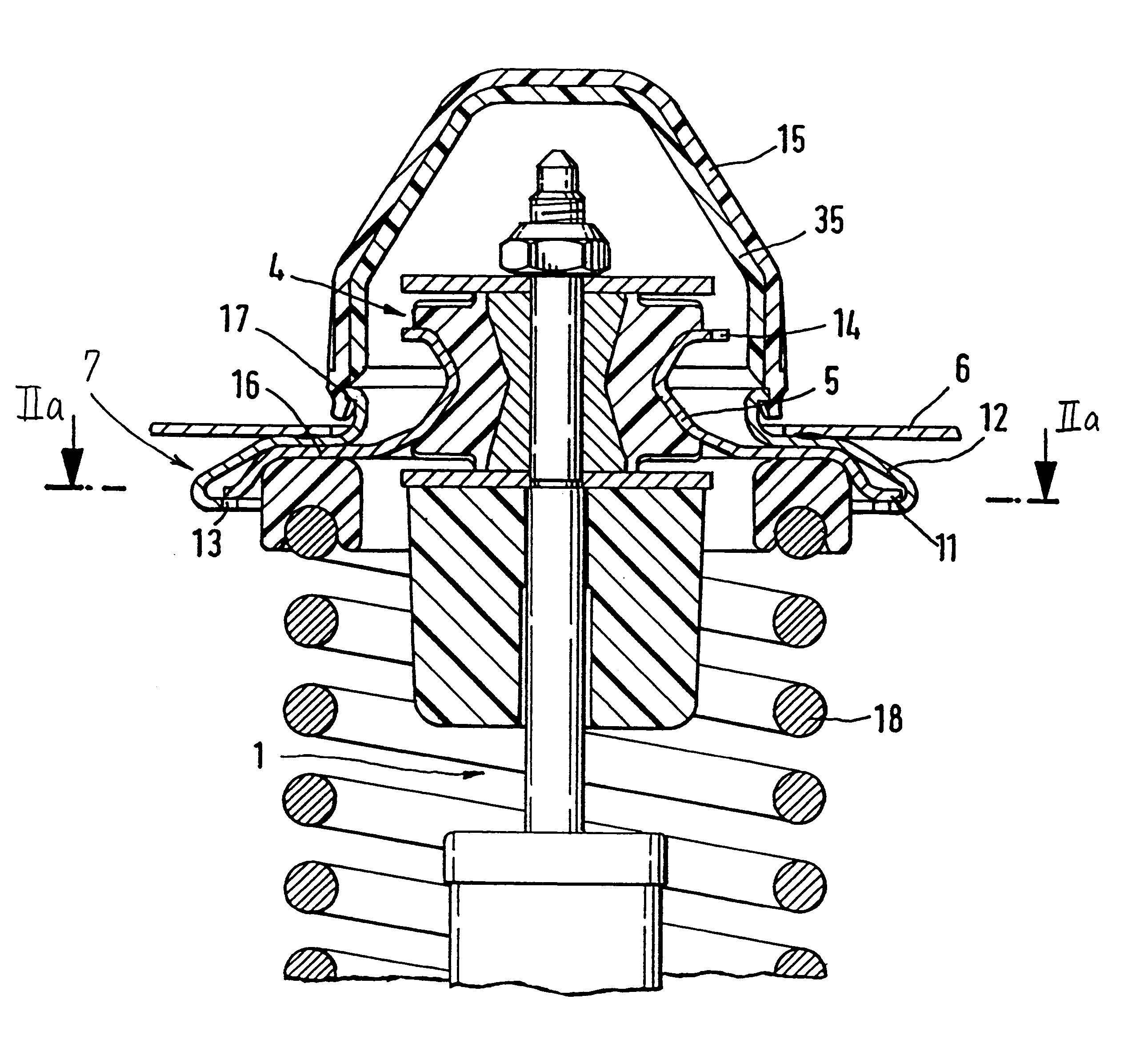
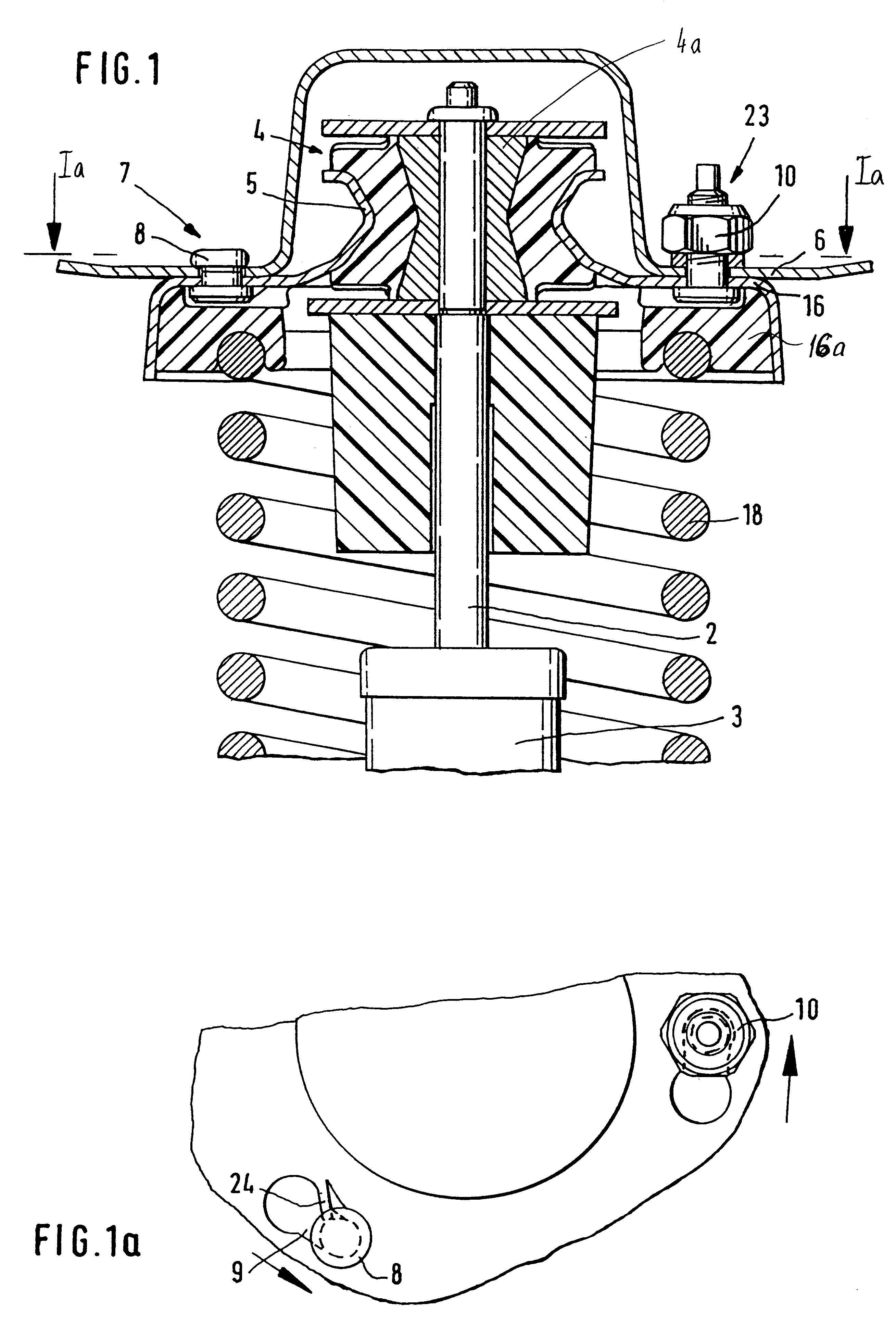
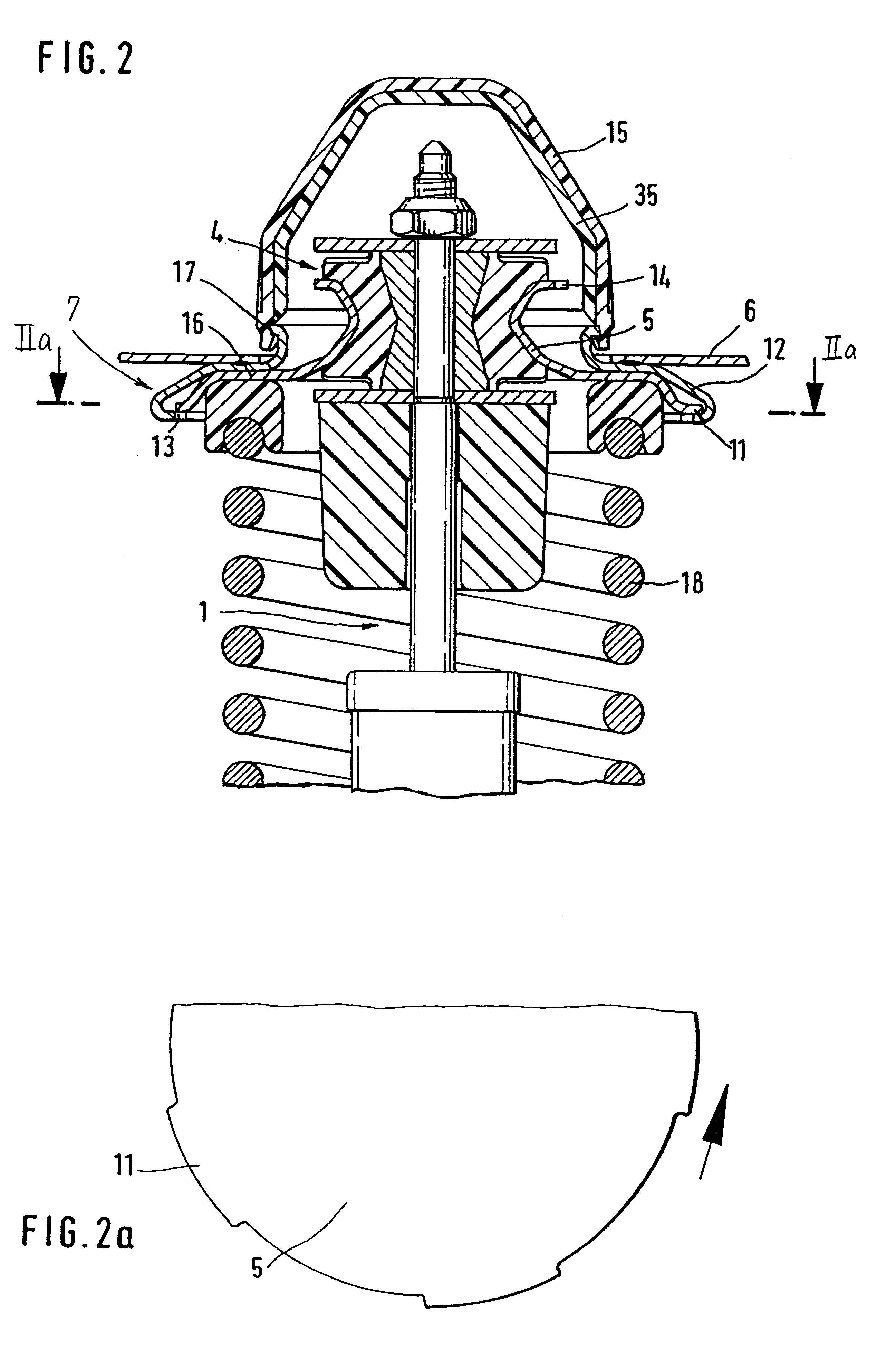
FIG. 1 shows an embodiment of a quick connection 7 for connecting a vibration damper such, for example, as a shock strut 1 with a vehicle body 6 of a motor vehicle. An elastic joint 4 constructed as a pin joint is mounted between a connection part 5 and a piston rod 2 guided in a cylinder 3. The connection part 5 is connected with a joint buffer 4a of the pin joint which is riveted to the piston rod 2. Rivet bolts 8 and connecting part 5 forms a spring plate 16 for receiving a supporting spring 18, including the elastic spring support 16a. As is shown in FIG. 1a, the vehicle body 6 is provided with receiving slots 9. Each of these receiving slots 9 has an opening which is adapted to the head of an associated rivet bolt 8 and a slot which corresponds to the shank of the rivet bolt 8. The slot extends circumferentially about a longitudinal axis of the shock strut 1. The longitudinal axis is preferably a central axis but may also be any longitudinal axis of the shock strut 1. As depict...


PUM


Abstract

The invention is directed to a vibration damper such as a shock strut for articulated installation between a car body and a wheel guide part in a motor vehicle by a quick connection. For this purpose, the vibration damper on the shock strut, together with an elastic joint and a connection part, forms a constructional unit or assembly unit. The quick connection is formed between the connection part and the body or the wheel guide without a catch connection and in a rigid manner, so that relative movement is prevented between the connection part and the body or wheel guide part.

Description

1. Field of the InventionThe invention is directed to a vibration damper or, more specifically, a shock strut for articulated installation between a car body and a wheel guide part in a motor vehicle. The vibration damper has a piston rod sealably guided in a cylinder. The connections between the vibration damper and the car body and the wheel guide are made using an elastic joint. The elastic joint and the vibration damper form a constructional unit that is connected to the wheel guide part or the car body by a quick connection.2. Description of the Related ArtTo simplify the assembly of shock struts or vibration dampers, it is desirable for the vibration dampers to form together with the elastic joint, an assembly unit that can be installed by an easy assembly step which can preferably be carried out by an assembly robot.Reference DE 44 40 030 A1 shows a simple assembly of a vibration damper or shock strut of the type mentioned above forming a constructional unit with the elastic ...

Claims


Application Information

Patent Timeline
IPC IPC(8): B60G15/06B60G13/00B60G15/00
CPCB60G13/005B60G15/067B60G2204/4602B60G2204/416B60G2204/44B60G2204/128
Inventor ANGLES, MANFREDHANDKE, GUNTHERPRADEL, ROBERT
Owner MANNESMANN SACHS AG
Why Eureka
Try Eureka