Dual speed motor drive circuit

Inactive Publication Date: 2001-07-17
HITACHI GLOBAL STORAGE TECH NETHERLANDS BV
View PDF11 Cites 31 Cited by
  • Summary
  • Abstract
  • Description
  • Claims
  • Application Information

AI Technical Summary

Problems solved by technology

However, unlike AC power, battery power will get depleted as the notebook is being operated.
The trade-off for this lower power consumption is a decrease in RPM of the spindle motor which directly leads to a decreased performance in data access time.
However, a linear motor driver is the least efficient when operated at low RPMs which runs counter to the goal of minimizing power consumption at low RPM.
At low RPM, there is a significant voltage drop in the motor driver due to the decrease in back-emf as illustrated in voltage plot 10, resulting in significant energy dissipation (illustrated in power plot 20) in the motor driver's output transistors and therefore efficiency is very low.
However, using a spindle motor that is optimized for low RPM at the standard +5.0 V supply voltage would mean that the spindle motor would not be able to run at a higher RPM at this standard voltage.
This is undesirable when high performance is required.
As illustrated, there is a significant voltage drop and energy dissipation across the motor driver greatly reducing the efficiency.
However, DC--DC voltage step down converters usually have efficiency rates of only 80-90% thereby introducing a new power loss, which negates some of the gained efficiency.
Thus, using a DC--DC down converter in the low RPM mode to lower the effective supply voltage which introduces efficiency losses is undesirable.
The high speed mode of dual-speed drives typically require 7200-10,000 RPM, which is often beyond the capability of a conventional +5.0 V spindle motor.
None of the prior art mentioned above is capable of producing the highest efficiency at low RPM speeds without introducing new power losses.
Although the DC--DC step up converter introduces a new power loss, this is insignificant since power is practically unlimited when AC power is used.

Method used


Image

  • Dual speed motor drive circuit
  • Dual speed motor drive circuit
  • Dual speed motor drive circuit

Examples


Embodiment Construction

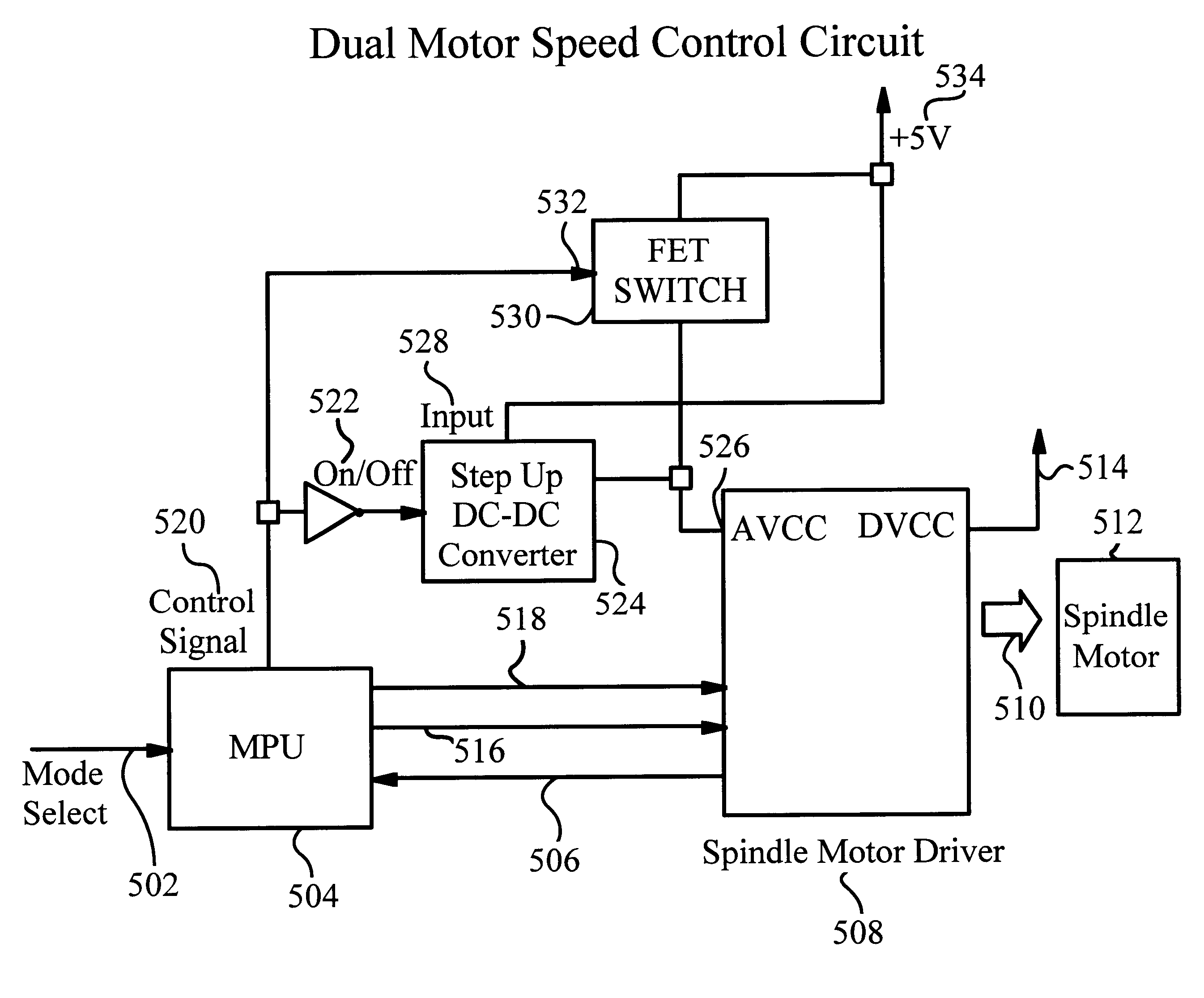
Although the invention is described as embodied in a hard disk drive with a spindle motor, the invention also applies to other motor systems and applications requiring dual / multiple speed controls such as CD-ROM drives, DVD drives, floppy disk drives, and even video camcorders for example. Accordingly, the following preferred embodiment of the invention is set forth without any loss of generality to, and without imposing limitations upon, the claimed invention.

The present invention uses a spindle motor optimized to operated at the maximum efficiency with the full +5.0 V supply voltage for low RPM operation, and uses a voltage conversion circuitry to increase the standard +5.0 V supply voltage for higher RPM operation. Although the use of voltage conversion circuitry introduces some efficiency losses, unlike in the low RPM mode, this efficiency loss in the high RPM mode is insignificant as unlimited AC power is available.

Therefore, the use of a DC--DC step up converter not only allow...


PUM


Abstract

A dual speed hard drive system designed to operate at the highest efficiency in the low RPM mode, and at the highest performance in the high RPM mode. To achieve the highest efficiency in the low RPM mode, the spindle motor is optimized for maximum efficiency for low RPM speeds using the standard supply voltage of +5.0 V. To achieve the highest performance, a DC-DC step up converter increases the supply voltage to beyond the standard +5.0 V supply voltage thereby allowing the spindle motor to achieve a higher RPM. A 2-stage spin up process is utilized when the spindle motor is retired to go from a stationary state to the high RPM mode. This 2-stage spin up process minimizes the power capacity requirement and the thermal rise of the DC-DC step up converter during operation.

Description

The present invention relates to the spindle motor control in hard disk drives and more particularly to dual mode spindle motor control in hard disk drives to provide a high-efficiency mode and a high-performance mode in portable computing devices.DESCRIPTION OF THE RELATED ARTPortable computing devices, particularly notebook computers, are gaining popularity in recent years due to their compact size, weight, and mobility. Notebook computers can operate either from AC power or from battery power. However, unlike AC power, battery power will get depleted as the notebook is being operated. The hard disk drive (HDD) is one of the devices in a notebook that uses large amounts of power when in operation. Therefore, the spindle motors in hard disk drives are intentionally operated at low speeds, measured in revolutions per minute (RPM), to minimize power consumption during battery operation. The trade-off for this lower power consumption is a decrease in RPM of the spindle motor which dir...

Claims


Application Information

Patent Timeline
IPC IPC(8): G11B19/26
CPCG11B19/26
Inventor YAMAMOTO, SATOSHI
Owner HITACHI GLOBAL STORAGE TECH NETHERLANDS BV
Why Eureka
Try Eureka