Autostereoscopic image acquisition method and system

a technology of image acquisition and image acquisition, applied in the field of autostereoscopic image acquisition method and system, can solve the problems inconvenient use, and no technical solution, and achieve the effect of large computer power consumption, simple structure and high accuracy

Inactive Publication Date: 2001-07-17
ALIOSCOPY
View PDF5 Cites 36 Cited by
  • Summary
  • Abstract
  • Description
  • Claims
  • Application Information

AI Technical Summary

Benefits of technology

An object of the present invention is thus to provide a method of acquiring si

Problems solved by technology

Methods of stereoscopic simulation having two view-points have been proposed, e.g. in European patent applications numbers EP-125 480 (HONEYWELL) and EP-172 110 (GIRAVIONS DORAND), however they operate by storing stereoscopic half-images and are therefore not suitable for use with the above-mentioned software.
At present, when displaying stored data as defined above, there is no technical solution making it possible to simulate a display in relief under conditions of visual comfort that enable the autostereoscopic effect to be visible at

Method used


Image

  • Autostereoscopic image acquisition method and system
  • Autostereoscopic image acquisition method and system
  • Autostereoscopic image acquisition method and system

Examples


example i

Real camera: focal length of real objective lens system to be simulated=200 mm; aperture f / 2; image width=57.6 mm, pixel size=0.1 mm; number n of viewpoints=4.

Focusing can begin at twice the focal length, i.e. 400 mm. This leads to images having the same size in the physical image plane as the filmed objects. The theoretical stereoscopic field of the apparatus with four viewpoints extends between 384 mm and 416 mm. An object whose image has a horizontal dimension equal to one apparent pixel (in fact a lens that is 0.4 mm wide) forms its image at the focal plane on one lens only, and all four pixels are used. If an object is placed at the limits of the theoretical stereoscopic depth of field:

at the lower limit (384 mm), the object appears to stand out from the display screen, the image occupies four lenses with a single pixel per lens as follows:

pixel positions in the columns of four: ##EQU3##

at the upper limit (416 mm), the object appears to be behind the screen and the image occupi...

example ii

Real camera: focal length=50 mm, aperture f / 2, image width=576.times.12.5 p; width of one pixel=12.5.mu.; four viewpoints. The focal length and the stereoscopic base are one-fourth of the values in Example I. The apparent magnification is therefore four. The field angle is halved.

Filming must be at one-fourth the distance to have the same angle 2.alpha.. In simulation, the stereoscopic base b is one-fourth its previous value. The disparity is the same, but the perceived size of background objects is a little large because of the change of field angle (which corresponds to a "zoom" effect). This does not matter since we are capable of correcting mentally so long as the effect is not too great (up to about three times). This evaluation takes account of the fact that we can move closer to the screen without difficulty to see the pairs (1 and 4) or to move away from it to see the pairs (1 and 2) or (2 and 3) or (3 and 4), with this giving rise to an apparent change of the angle subtende...


PUM


Abstract

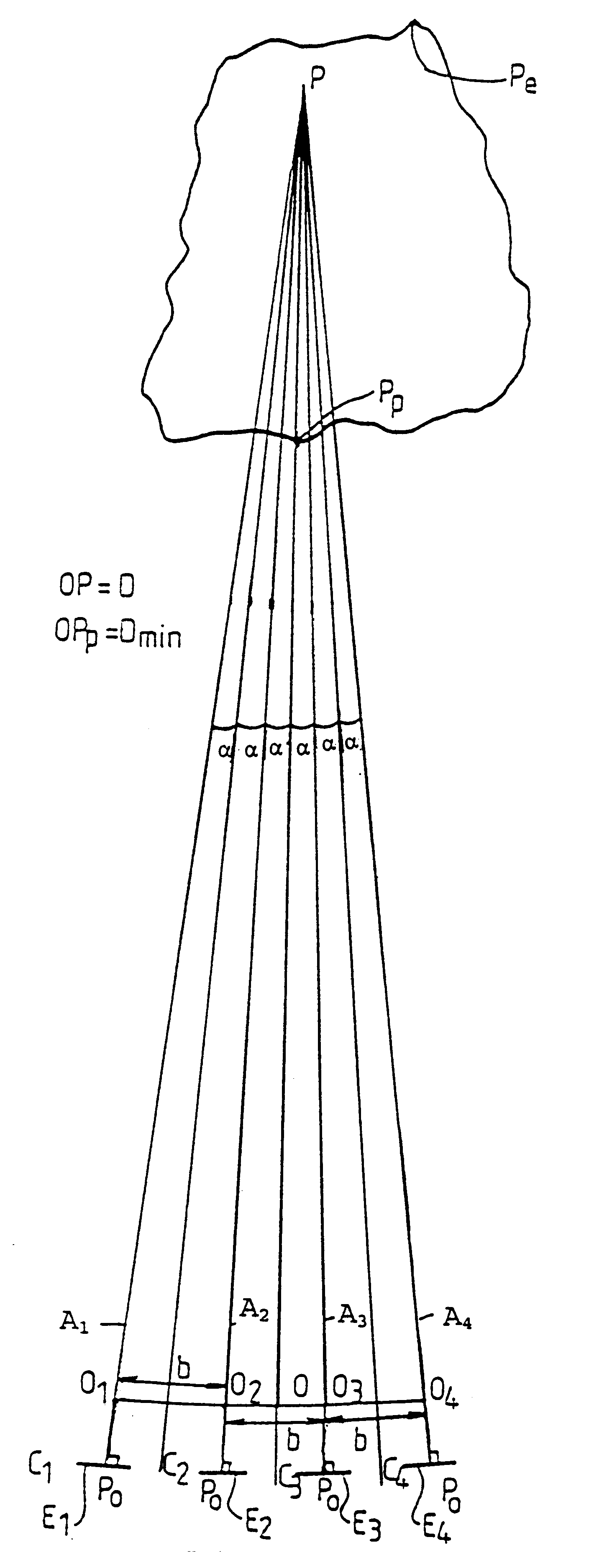
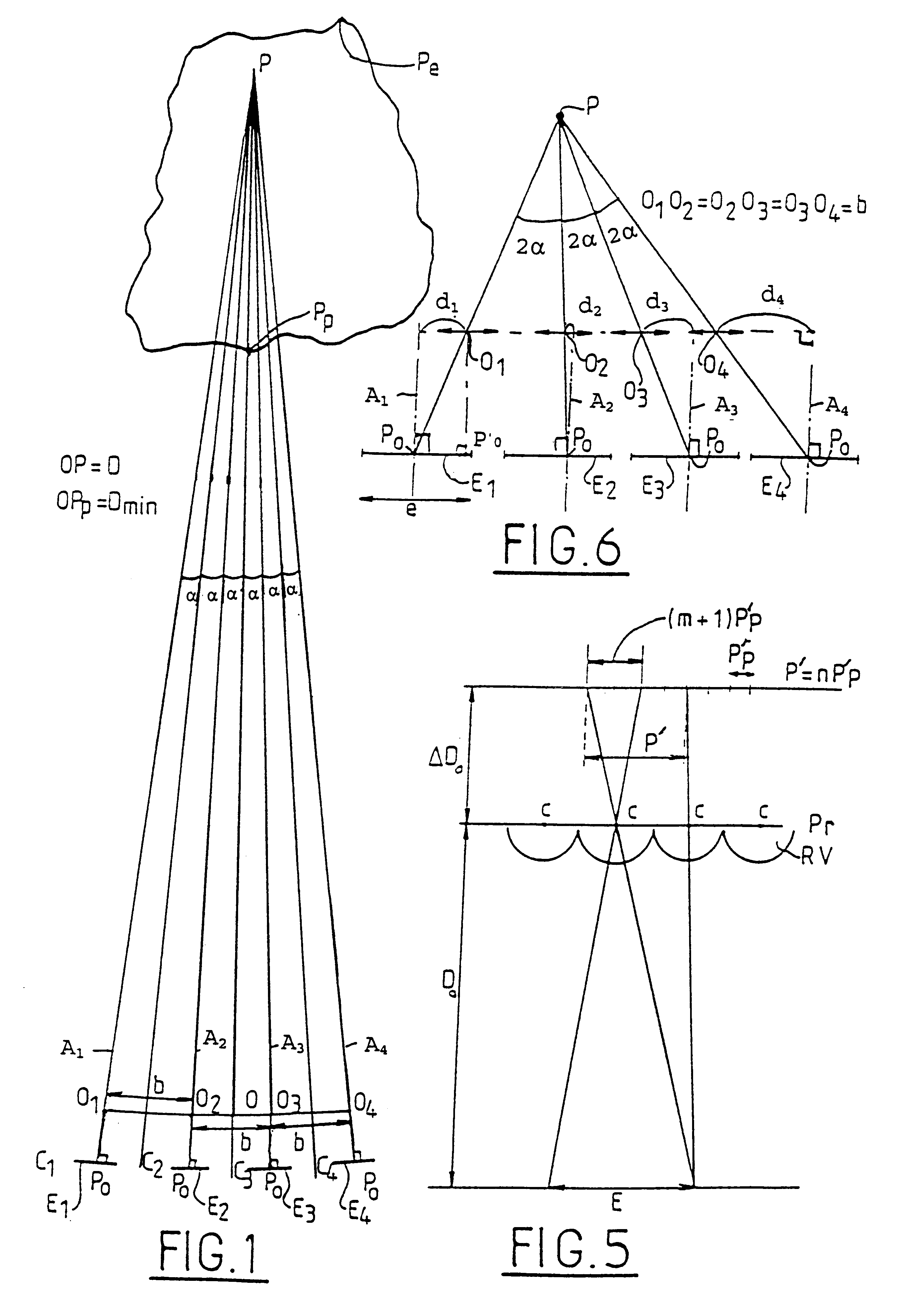
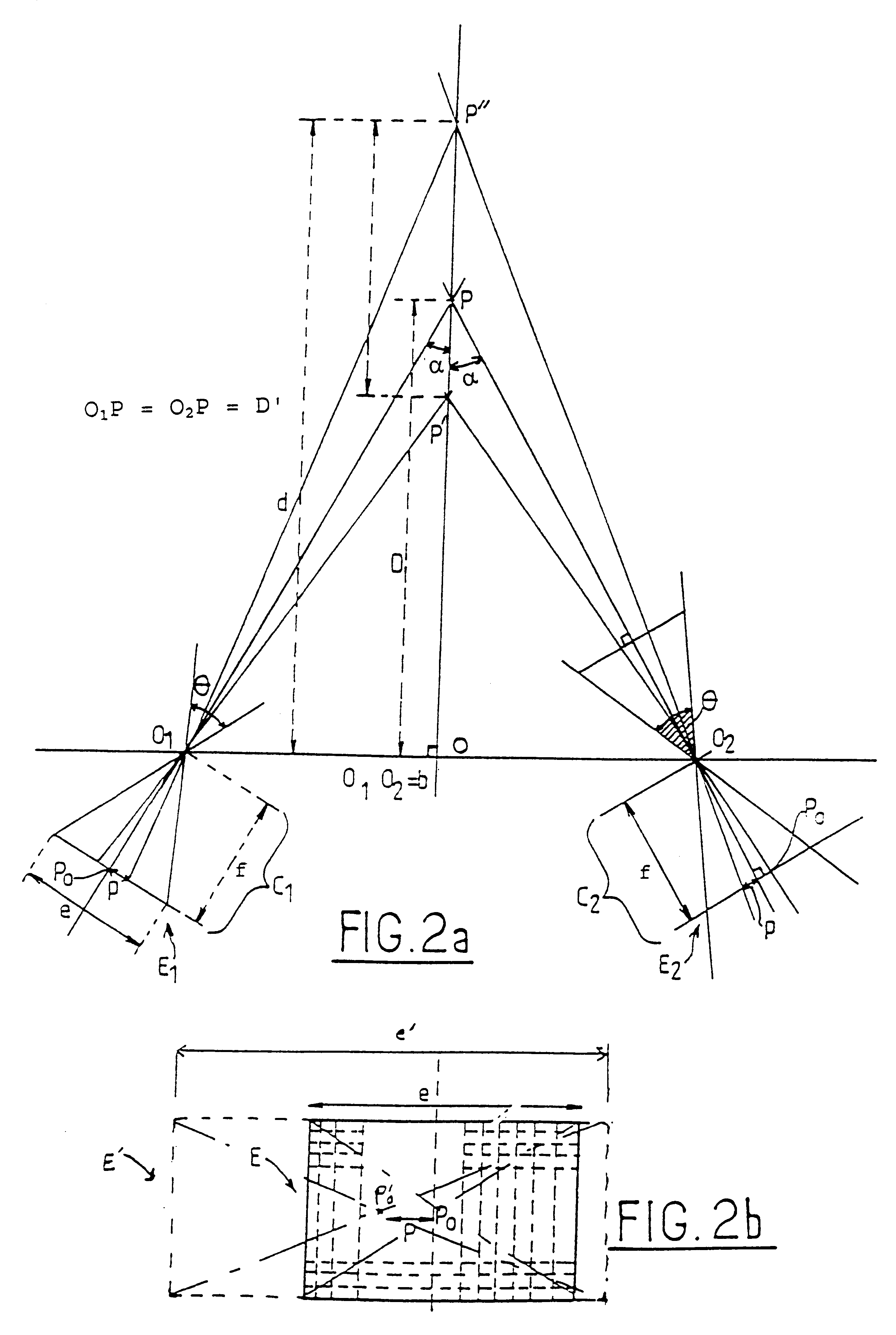
The invention relates to a method of acquiring simulated autostereoscopic video images of a scene to be viewed. On the basis of stored data containing three-dimensional information, it implements n simulated cameras, with n>=3, each generating an image of a scene on a given optical axis. The optical axes of the simulated cameras converge at a point situated at the same distance D from the simulated cameras. The scene to be viewed has a nearest point Pp and a farthest point Pe, and the inter-camera distance and the distance Dmin between the simulated cameras and the nearest point Pp are selected in such a manner that for focus varying between the nearest point Pp and the farthest point Pe the angle 2alpha between two adjacent simulated cameras varies between a value not greater than 4.5° for the point Pp and a value not less than 0.2° for the point Pe.

Description

The present invention relates to a method of acquiring simulated autostereoscopic video images.At present, there is a considerable amount of software on the market for computer-aided design (CAD) making it possible to store data corresponding to three-dimensional information about objects or a scene to be observed. The software incorporates processing means that enable only a flat image of the object or the scene to be viewed in perspective on a screen at angles of observation that can be selected at will.Methods of stereoscopic simulation having two view-points have been proposed, e.g. in European patent applications numbers EP-125 480 (HONEYWELL) and EP-172 110 (GIRAVIONS DORAND), however they operate by storing stereoscopic half-images and are therefore not suitable for use with the above-mentioned software.The Applicant has developed an autostereoscopic video system having more than two elementary images, also referred to as "viewpoints", typically presenting a number n of viewp...

Claims


Application Information

Patent Timeline
IPC IPC(8): H04N13/00G03B35/10G06T19/00H04N13/243H04N13/349H04N13/363
CPCH04N13/0014H04N13/0228H04N13/0239H04N13/0242H04N13/0278H04N13/0404H04N13/0445H04N19/597H04N13/0055H04N13/0059H04N13/0289H04N13/0431H04N13/0434H04N13/0438H04N13/0459H04N13/0475H04N13/0477H04N13/0481H04N13/004H04N13/337H04N13/341H04N13/289H04N13/305H04N13/243H04N13/194H04N13/279H04N13/189H04N13/376H04N13/156H04N13/229H04N13/38H04N13/117H04N13/349H04N13/334H04N13/363H04N13/373H04N13/239H04N13/00
Inventor ALLIO, PIERRE
Owner ALIOSCOPY
Why Eureka
Try Eureka