Excitation controller and excitation control method for stabilizing voltage in electric power system

a technology of excitation controller and control method, which is applied in the direction of control system, electric generator control, dynamo-electric converter control, etc., can solve the problems of reducing system reliability and increasing manufacturing cos

Inactive Publication Date: 2001-07-24
MITSUBISHI ELECTRIC CORP
View PDF16 Cites 23 Cited by
  • Summary
  • Abstract
  • Description
  • Claims
  • Application Information

AI Technical Summary

Problems solved by technology

However, it has a problem of increasing the manufacturing cost because of the expensive PD 10 which is required for detecting the transmission voltage V.sub.H of the transmission bus 5.
Furthermore, since an excitation control cubicle, on which the AVR 15 and adder

Method used


Image

  • Excitation controller and excitation control method for stabilizing voltage in electric power system
  • Excitation controller and excitation control method for stabilizing voltage in electric power system
  • Excitation controller and excitation control method for stabilizing voltage in electric power system

Examples


embodiment 1

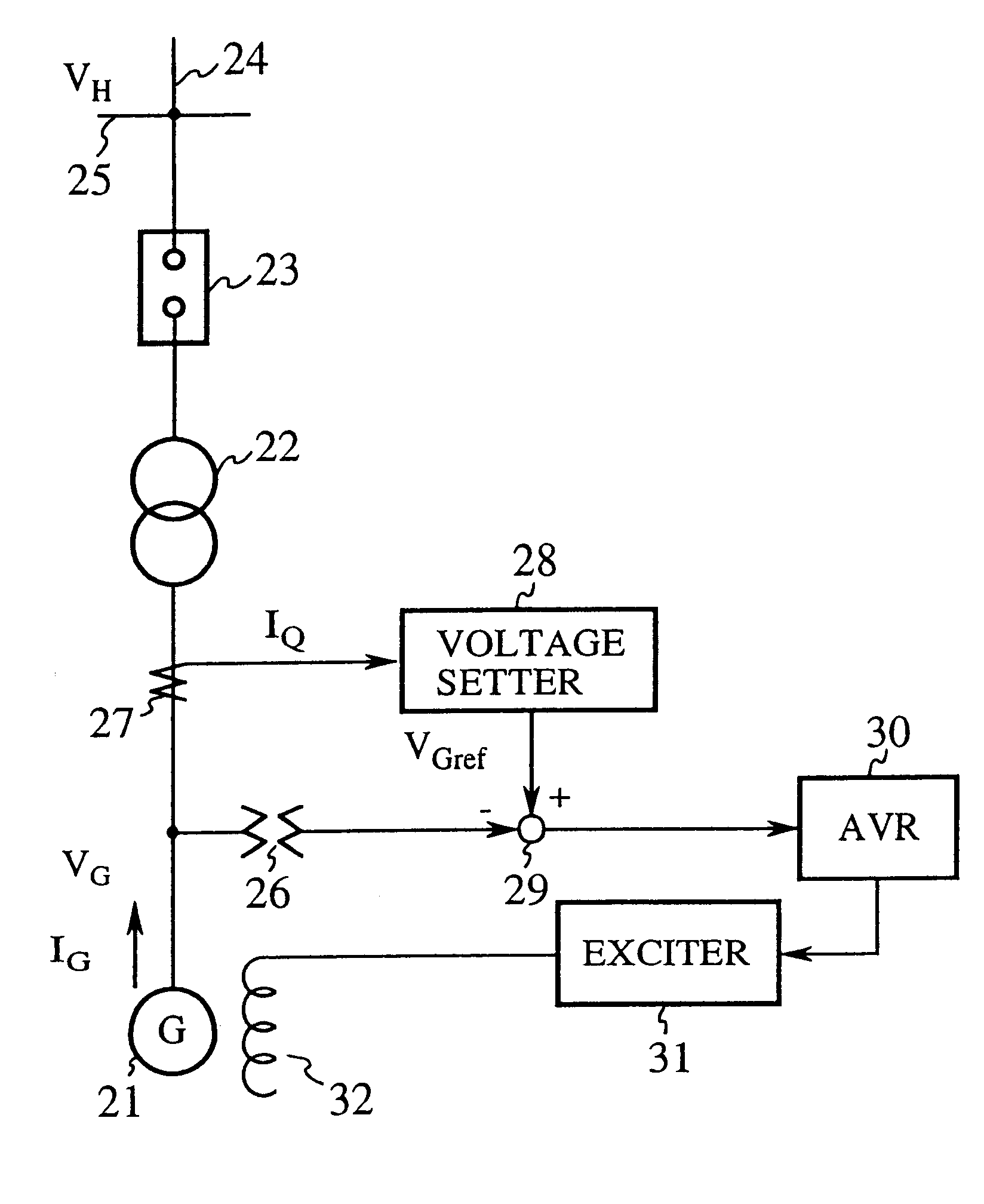
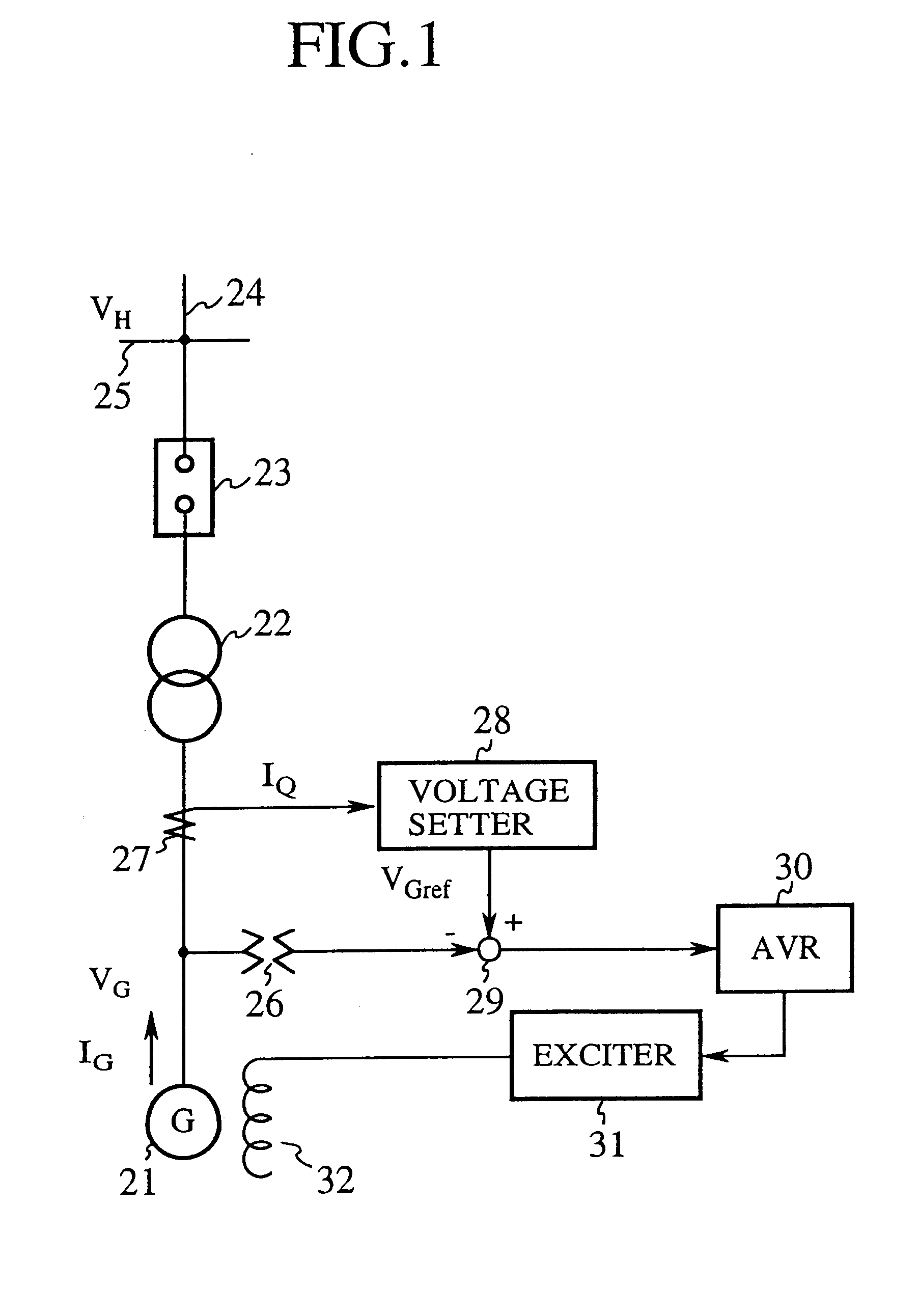
FIG. 1 is a block diagram showing an excitation controller in accordance with the present invention. In FIG. 1, the reference numeral 21 designates a synchronous machine; 22 designates a transformer; 23 designates a breaker; 24 designates a transmission line; 25 designates a transmission bus of a power plant; 26 designates a PT (potential transformer) for detecting the output terminal voltage V.sub.G of the synchronous machine 21; 27 designates a CT (current transformer) for detecting the reactive current I.sub.Q output from the synchronous machine 21; and 28 designates a voltage setter for setting the output terminal reference voltage V.sub.Gref in response to the reactive current I.sub.Q detected by the CT 27 and the high side reference voltage V.sub.Href of the transformer 22.

The reference numeral 29 designates a subtracter for subtracting from the reference voltage V.sub.Gref, set by the voltage setter 28, the output terminal voltage V.sub.G detected by the PT 26, and for output...

embodiment 2

The foregoing embodiment 1 sets the output terminal reference voltage V.sub.Gref of the synchronous machine 21 by substituting into equation (3) the reactive current I.sub.Q output from the synchronous machine 21 and the high side reference voltage V.sub.Href of the transformer 22. In this case, as illustrated by (1) of FIG. 6, the high sidevoltage V.sub.H of the transformer 22 agrees with the reference voltage V.sub.Href only when the reactive current I.sub.Q =0.

However, when the generation system is in the normal mode, because the reactive current I.sub.Q.noteq.0, it is impossible for the high side voltage V.sub.H of the transformer 22 to be made always equal to the reference voltage V.sub.Href.

In view of this, the present embodiment 2 sets the output terminal reference voltage V.sub.Gref of the synchronous machine 21 such that the high side voltage V.sub.H of the transformer 22 agrees with the reference voltage V.sub.Href when the reactive current I.sub.Q output from the synchron...

embodiment 3

Although the foregoing embodiment 2 employs the reference value I.sub.Q0 corresponding to the high side reference voltage V.sub.Href of the transformer 22, if the reference voltage V.sub.Href is changed from V.sub.Hrf1 to V.sub.Href2 in an operation mode in which the reference value I.sub.Q0 =I.sub.Q01 and the high side reference voltage of the transformer 22 V.sub.Href =V.sub.Href1 (when the reactive current I.sub.Q =I.sub.Q1, and the high side voltage of the transformer 22 V.sub.H =V.sub.H1), the high side voltage VH.sub.2 of the transformer 22 is expressed as follows because the reactive current I.sub.Q also changes from I.sub.Q1 to I.sub.Q2.

VH.sub.2 =V.sub.Href2 -X.sub.DR (I.sub.Q2 -I.sub.Q01) (9)

However, because I.sub.Q2.noteq.I.sub.Q01 in equation (9), the high side voltage VH.sub.2 of the transformer 22 does not agree with the altered reference voltage V.sub.Href2.

In view of this, the present embodiment 3 employs the reference value I.sub.Q02 corresponding to the altered refe...


PUM


Abstract

An excitation controller sets an output terminal reference voltage of a synchronous machine from a reactive current output from the synchronous machine and a high side reference voltage of a transformer, and controls the field current supplied to the field winding of the synchronous machine in response to the deviation between the reference voltage and the output terminal voltage. Although a conventional excitation controller can maintain the transmission voltage on the transmission bus at a fixed value, an expensive potential detector is needed for detecting the transmission voltage on the transmission bus, which increases the manufacturing cost of the excitation controller.

Description

1. Field of the InventionThe present invention relates to an excitation controller and an excitation control method for stabilizing voltage in an electric power system.2. Description of Related ArtFIG. 8 is a block diagram showing a conventional excitation controller disclosed in Japanese patent publication No. Hei. 10-2809833. In FIG. 8, the reference numeral 1 designates a synchronous machine; 2 designates a transformer; 3 designates a breaker; 4 designates a transmission line; 5 designates a transmission bus of a power plant; 6 designates a potential transformer (called "PT" from now on) for detecting an output terminal voltage V.sub.G of the synchronous machine 1; 7 designates a voltage setter for setting the output terminal reference voltage r.sub.G of the synchronous machine 1; 8 designates a subtracter for producing a deviation signal by subtracting the output terminal voltage V.sub.G from the reference voltage r.sub.G set by the voltage setter 7; and 9 designates a reduced g...

Claims


Application Information

Patent Timeline
IPC IPC(8): H02P9/30H02P9/14
CPCH02P9/305
Inventor KITAMURA, HITOMITANAKA, SEIICHISHIMOMURA, MASARU
Owner MITSUBISHI ELECTRIC CORP
Why Eureka
Try Eureka