Longest-edge refinement and derefinement system and method for automatic mesh generation

a technology of automatic mesh generation and refinement, applied in the field of longest-edge refinement and derefinement system and method for automatic mesh generation, can solve the problems of inaccurate numerical approximation and increasing difficulty in accurate approximation

Inactive Publication Date: 2001-07-24
RIVARA MARIA CECILIA
View PDF4 Cites 47 Cited by
  • Summary
  • Abstract
  • Description
  • Claims
  • Application Information

AI Technical Summary

Benefits of technology

The derefinement method, for each target vertex finding an associated set of neighbor vertices to be derefined; then eliminating each said vertex according an appropriate order such that the derefinement of said vertex allows to re-obtain a previous terminal edge whose bisection produced said vertex. The method, mesh data structure and apparatus of this invention allowing the parallel scalable refinement / derefinement of the mesh by locally modifying sets of neighbor elements sharing the common longest-edge.

Problems solved by technology

Finite element analysis is specially important when the geometry of the object to be modeled is relatively complex, e.g. includes small details, since the differential equations for such applications become increasingly difficult to approximate accurately.
It is known that the generation of a 3-D mesh suitable for finite element analysis has been one of the most time consuming steps in using the computer to analyze a complex engineering problem.
Quality is a very important factor since a bad-quality mesh can result in inaccurate numerical approximation.

Method used


Image

  • Longest-edge refinement and derefinement system and method for automatic mesh generation
  • Longest-edge refinement and derefinement system and method for automatic mesh generation
  • Longest-edge refinement and derefinement system and method for automatic mesh generation

Examples


Embodiment Construction

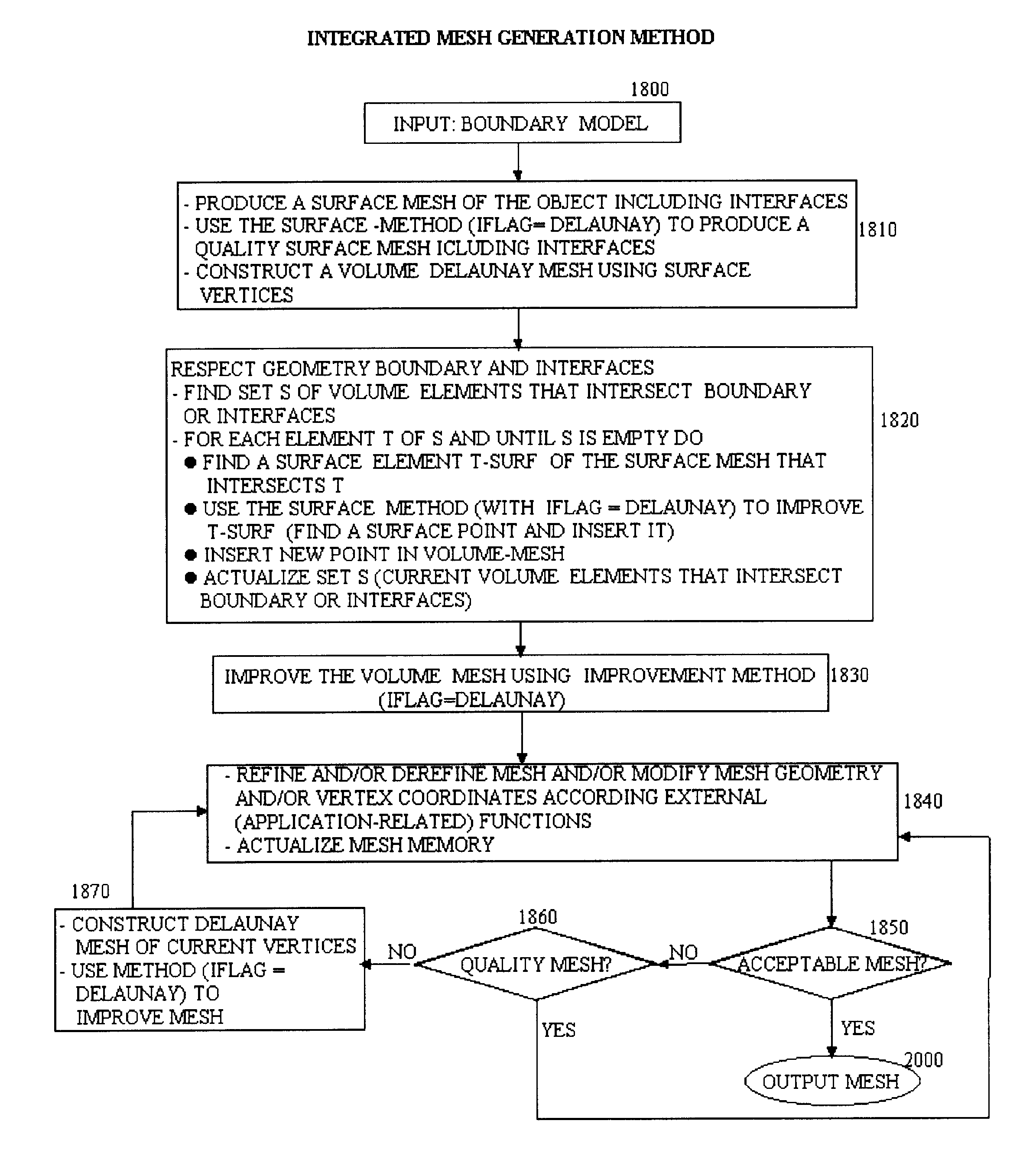
This invention comprises an improvement / refinement method, a derefinement method, a mesh data structure, an integrated automated mesh generation method, and apparatus therefor.

Even when every component of this invention takes full advantage of the terminal-edge abstraction of a mesh of elements and its geometrical properties, and all these components can be adequately integrated to produce a flexible and automatic mesh generation system, the improvement component, the refinement component and the refinement / derefinement component can stand alone independent of each other in the sense that these components can be used separately in different applications. The derefinement method however only can be used to derefine meshes produced throughout the previous use of the longest-edge refinement method, and in this sense includes and generalizes the refinement method.

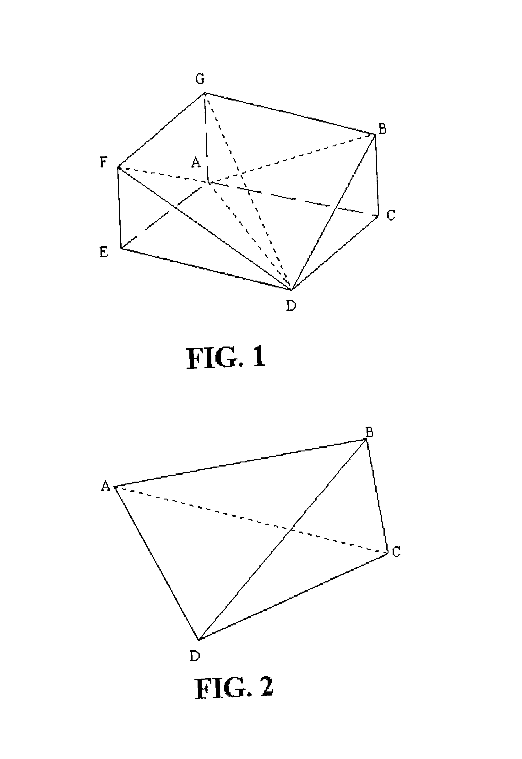
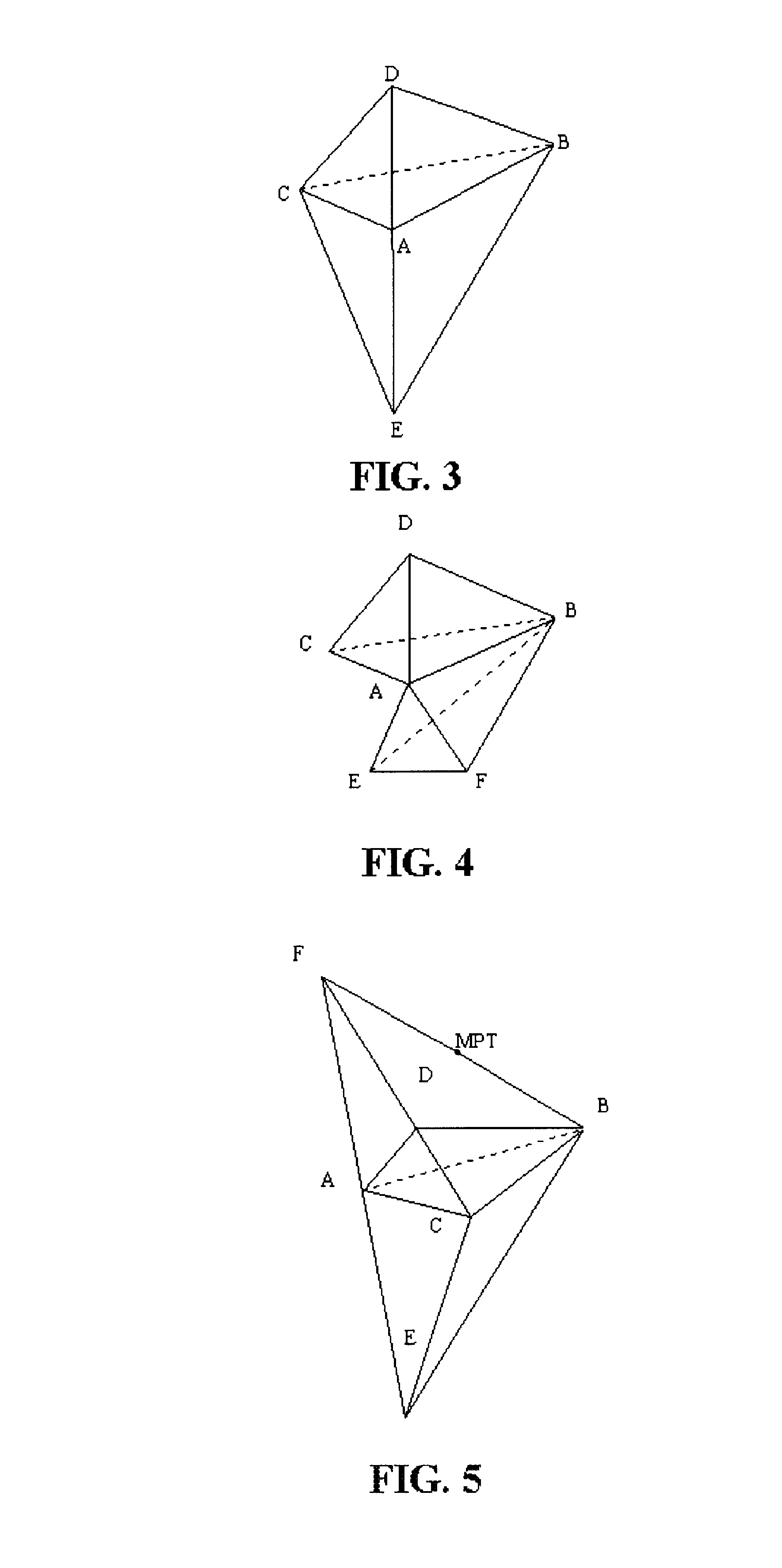
FIG. 1 to FIG. 5 refer to some geometrical issues of the method and apparatus of the present invention.

Referring to FIG. 1, a...


PUM


Abstract

A method, mesh data structure and apparatus is disclosed for producing an improved/refined/derefined mesh of finite elements for a three-dimensional object showing boundaries and faces. The improvement/refinement method repeatedly searching, for consecutive sets of active target elements to be refined or improved, an associated submesh and set of terminal edges, the searching process not modifying the mesh data structure; then according to the point insertion method chosen, selection of the point or the points to be inserted between the midpoints of the terminal edges modified by some boundary considerations; inserting the selected point or points in the initial mesh; and then proceeding to the succeeding set of active target elements until an user-defined stopping criterion is achieved.The derefinement method, for each target vertex finding an associated set of neighbor vertices to be derefined; then eliminating each said vertex according an appropriate order such that the derefinement of said vertex allows to re-obtain a previous terminal edge whose bisection produced said vertex. The method, mesh data structure and apparatus of this invention allowing the parallel scaleable refinement/derefinement of the mesh by locally modifying sets of neighbor elements sharing the common longest-edge.

Description

This invention relates to the computer geometric modeling of a body as needed through the use of finite element analysis. In particular the invention relates to the generation of an improved and / or refined and / or derefined mesh of finite elements using an improved and flexible mesh generation method, an improved mesh data structure, and an apparatus therefor.Finite element analysis is a powerful computer-aided tool for solving engineering and physical problems governed by partial differential equations. Finite element analysis is used in approximating any continuous physical characteristic of an object or a geometric region, such as temperature, heat, vibration, fluid flow, electric field, pressure, etc. Finite element analysis is specially important when the geometry of the object to be modeled is relatively complex, e.g. includes small details, since the differential equations for such applications become increasingly difficult to approximate accurately.An initial step of a finite...

Claims


Application Information

Patent Timeline
Patent Type & Authority Patents(United States)
IPC IPC(8): G06T17/20
CPCG06T17/20
Inventor RIVARA, MARIA-CECILIA
Owner RIVARA MARIA CECILIA
Why Eureka
Try Eureka