Coupling structure of variable length shaft

a technology of variable length shaft and coupling structure, which is applied in the direction of couplings, rod connections, manufacturing tools, etc., can solve the problems of working accuracy, difficulty in adjusting lengths, and possible backlash between the intermediate shaft and the pipe member

Inactive Publication Date: 2001-07-31
NSK LTD
View PDF12 Cites 29 Cited by
  • Summary
  • Abstract
  • Description
  • Claims
  • Application Information

AI Technical Summary

Problems solved by technology

On such spline-fitting or the like, a "backlash" might occur to some extent between the intermediate shaft and the pipe member due to factors such as a limit of working accuracy etc.
This might lead to a difficulty of adjusting lengths of the intermediate shaft and the pipe member in the axial direction and to a decline of workability.

Method used


Image

  • Coupling structure of variable length shaft
  • Coupling structure of variable length shaft
  • Coupling structure of variable length shaft

Examples


first embodiment

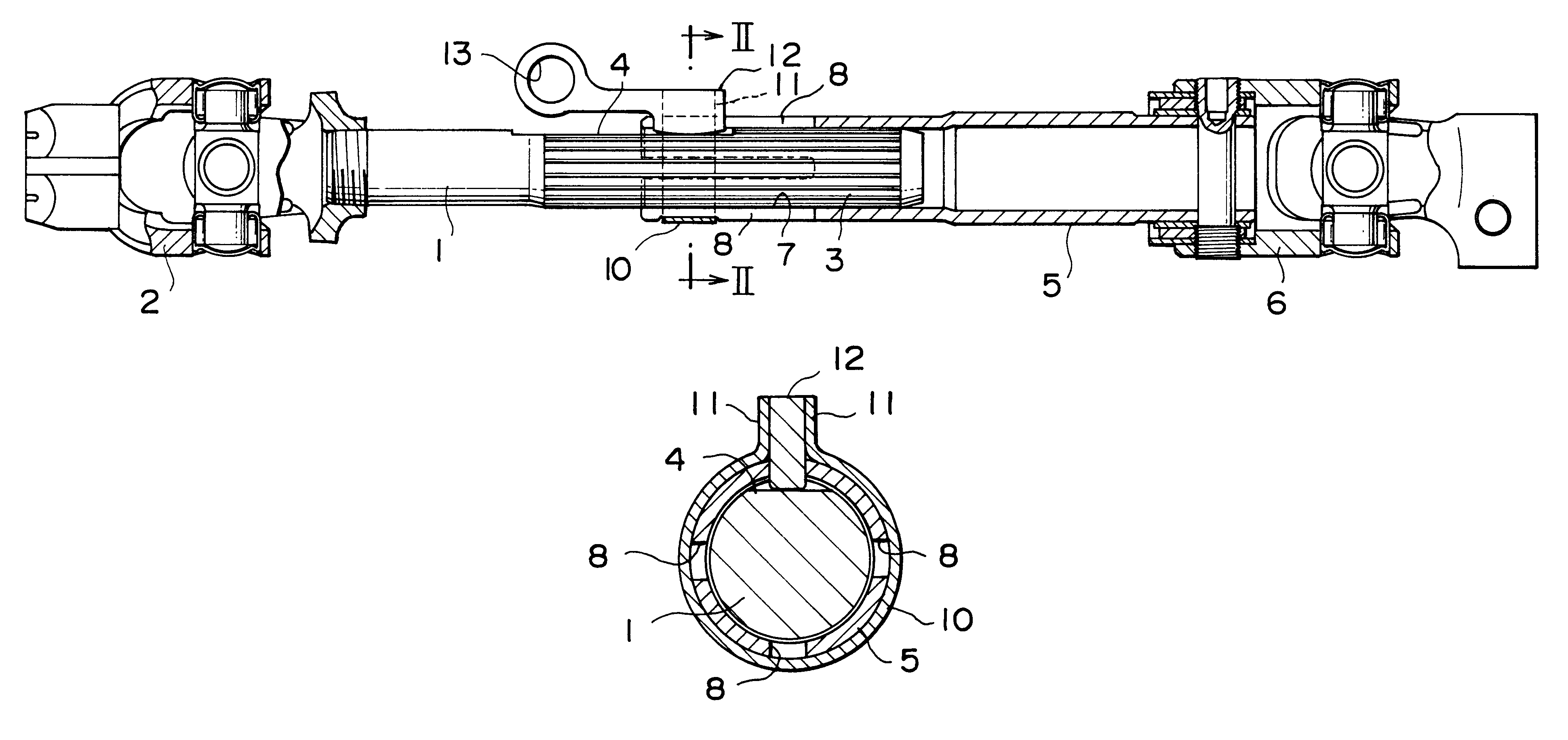
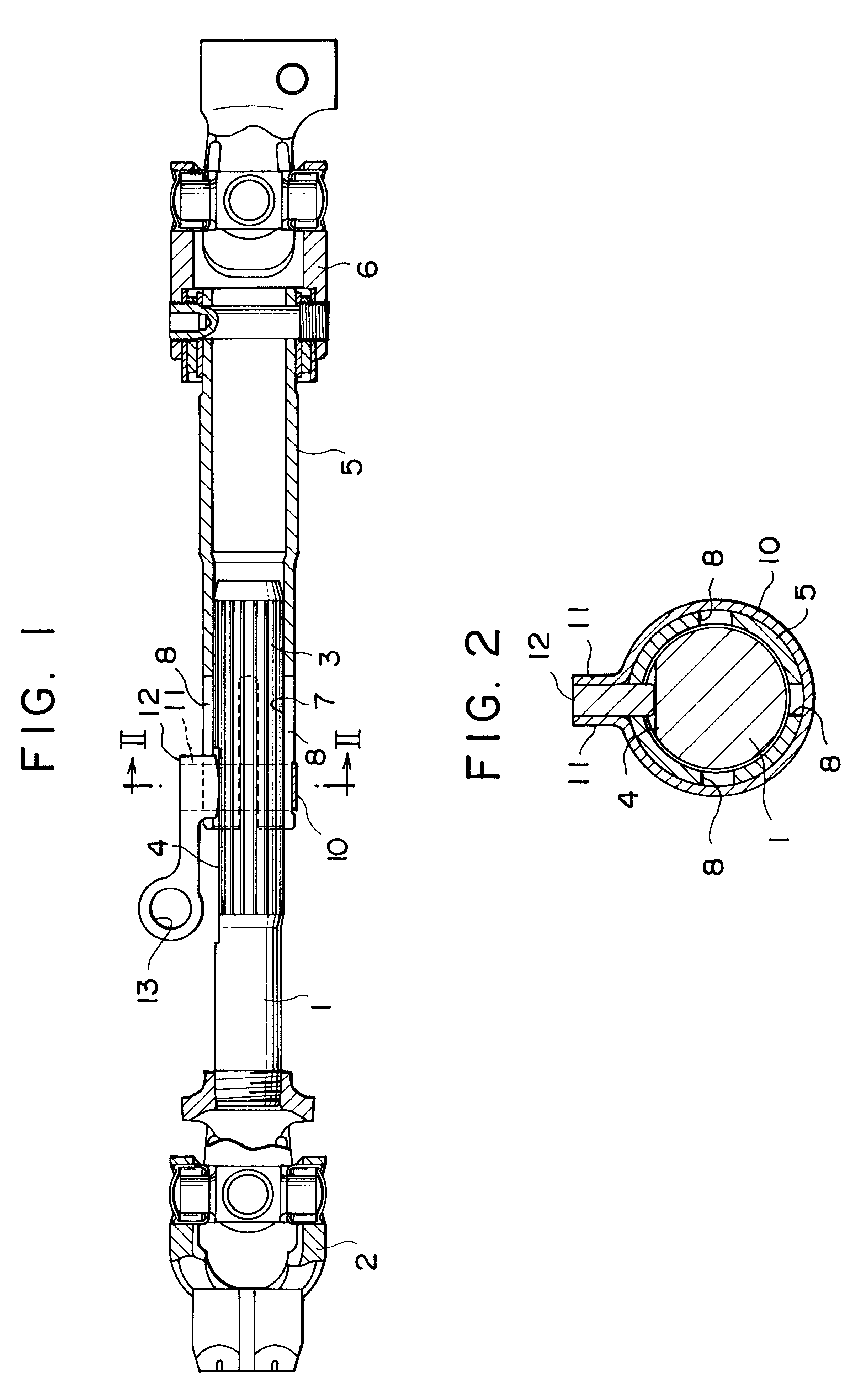
In the first embodiment, the holder 12 is sandwiched in between the pair of flat plate edges 11, 11 and is, as will hereinafter be described, provided with a manipulation ring 13 for pulling out the holder 12 with a finger of the worker.

The mechanism being thus structured, when assembling the steering device into the vehicle, the holder 12 is sandwiched in between the pair of flat plate edges 11, 11 of the ring member 10, thereby enlarging the width between the pair of flat plate edges 11, 11. This brings the ring member 10 into a state where the ring member 10 expands in diameter resisting its own elasticity and does not press the pipe member 5 inwards in the radial direction, where a slide frictional resistance of the pipe member 5 against the intermediate shaft 1 can be reduced. It is therefore feasible to make the intermediate shaft 1 freely easily slide on the pipe member 5, and enhance the workability when assembling the intermediate shaft 1 into the automobile.

On the other ha...

second embodiment

FIG. 4 is a vertical sectional view showing a coupling structure of the intermediate shaft in the steering device in the present invention. FIG. 5 is a sectional view taken along the line V--V in FIG. 4.

As shown in FIG. 4, a holder 20 acting as a "lever" is provided in the second embodiment, and a side end of this lever-like holder 20 is sandwiched in between the pair of flat plate edges 11, 11 of the ring member 10.

The lever-like holder 20 is provided with a first arm 22 formed with an elongate hole 21 through which a wire 25 which will be mentioned later on slides, and a second arm 23 serving as a manipulation member pressed by the worker to release the holder 20.

Moreover, a circumferential groove 24 formed in the intermediate shaft 1 is wound with one string of wire 25 exhibiting the elasticity, and this wire 25 engages with the elongate hole 21 of the first arm 22 described above.

With this configuration, when incorporating the steering device into the vehicle, the end of the fir...

third embodiment

FIG. 7 is a vertical sectional view illustrating the coupling structure of the intermediate shaft in the steering device in the present invention. FIG. 8 is a side view showing the holder used in the coupling structure shown in FIG. 7. FIG. 9 is a plan view showing the principal portion of the coupling structure illustrated in FIG. 7.

As shown in FIG. 7, a disk-like holder 30 having a rotary structure is provided in the third embodiment. The holder 30 is so structured as to be rotatable about a rotary shaft 31. The disk-like holder 30 is provided with a wall-thick portion 32 taking a circular arc on one side of the rotary shaft 31, and a wall-thin portion 33 assuming the circular arc on the other side of the rotary shaft 31. A knob 34 extends from the wall-thin portion 33. A supporting portion 35 fitted into the slit 8 of the pipe member 5 is provided under the disk-like holder 30.

With this configuration, when assembling the steering device into the vehicle, the disk-like holder 30 i...


PUM


Abstract

A coupling structure of a variable length shaft, comprises a pipe member having an end formed with a plurality of slits elongated in the axial direction to be capable of expanding and diminishing in diameter, an intermediate shaft spline-fitted in the end of the pipe member, and a ring member fitted on an outer periphery of the end of the pipe member, the intermediate shaft being fastened by the end of the pipe member. A holder is releasably attached to an end of the ring member to expand a diameter thereof and thereby reduce a slide frictional resistance of the pipe member against the intermediate shaft. When the holder is released, the ring member diminishes in diameter, and a fastening force of the pipe member on the intermediate shaft is increased.

Description

This application claims the benefit of Japanese Patent Applications No. 10-212029 and 11-79040 which are hereby incorporated by reference.1. Field of the InventionThe present invention relates generally to a coupling structure of a variable length shaft used for a steering device etc of an automobile, and more particularly to a coupling structure of a variable length shaft capable of enhancing a workability when assembling the steering device into a vehicle and surely preventing a "backlash" from being caused after having incorporated the steering device.2. Related Background ArtA steering device of an automobile is structured such that an intermediate shaft of a steering shaft is contractible upon a collision etc of the vehicle, thus protecting the driver. More specifically, the intermediate shaft of the steering shaft is spline- or serration-fitted to a pipe member provided posterior to the intermediate shaft, and when the collision happens, the intermediate shaft is retracted int...

Claims


Application Information

Patent Timeline
Patent Type & Authority Patents(United States)
IPC IPC(8): B62D1/16F16D3/02F16C3/02F16C3/03F16D3/06F16B7/04F16D1/02
CPCB62D1/16F16C3/03F16D3/06F16B7/0413Y10T403/7028Y10T403/7033Y10T403/7071
Inventor HIGASHINO, KIYOHARU
Owner NSK LTD
Why Eureka
Try Eureka