
Connector connecting structure

Inactive Publication Date: 2001-08-07
YAZAKI CORP
View PDF10 Cites 10 Cited by
  • Summary
  • Abstract
  • Description
  • Claims
  • Application Information

AI Technical Summary

Benefits of technology

In view of the foregoing, an object of the present invention is to provide a connector connecting structure which is superior in connecting workability of connectors and in positioning of connectors at coupling operation thereof.
According to the above-described structure, connection work of the connectors equipped on a vehicle can be performed easily and stable with the coupling operation described hereinbefore.

Problems solved by technology

Firstly, on connection of connectors, since pushing operation of the slider is required, work step increases, which makes assembling process rather complex. And, this lowers an efficiency of assembly work of members having the connectors.
Even if position precision is going to be raised in the present situation, in case of location where a lot of members are related to, the above problems cannot be readily canceled because dimension tolerance of each member affects each other.

Method used


Image

  • Connector connecting structure
  • Connector connecting structure
  • Connector connecting structure

Examples


Embodiment Construction

An embodiment of the present invention will now be described in further detail with reference to the accompanying drawings.

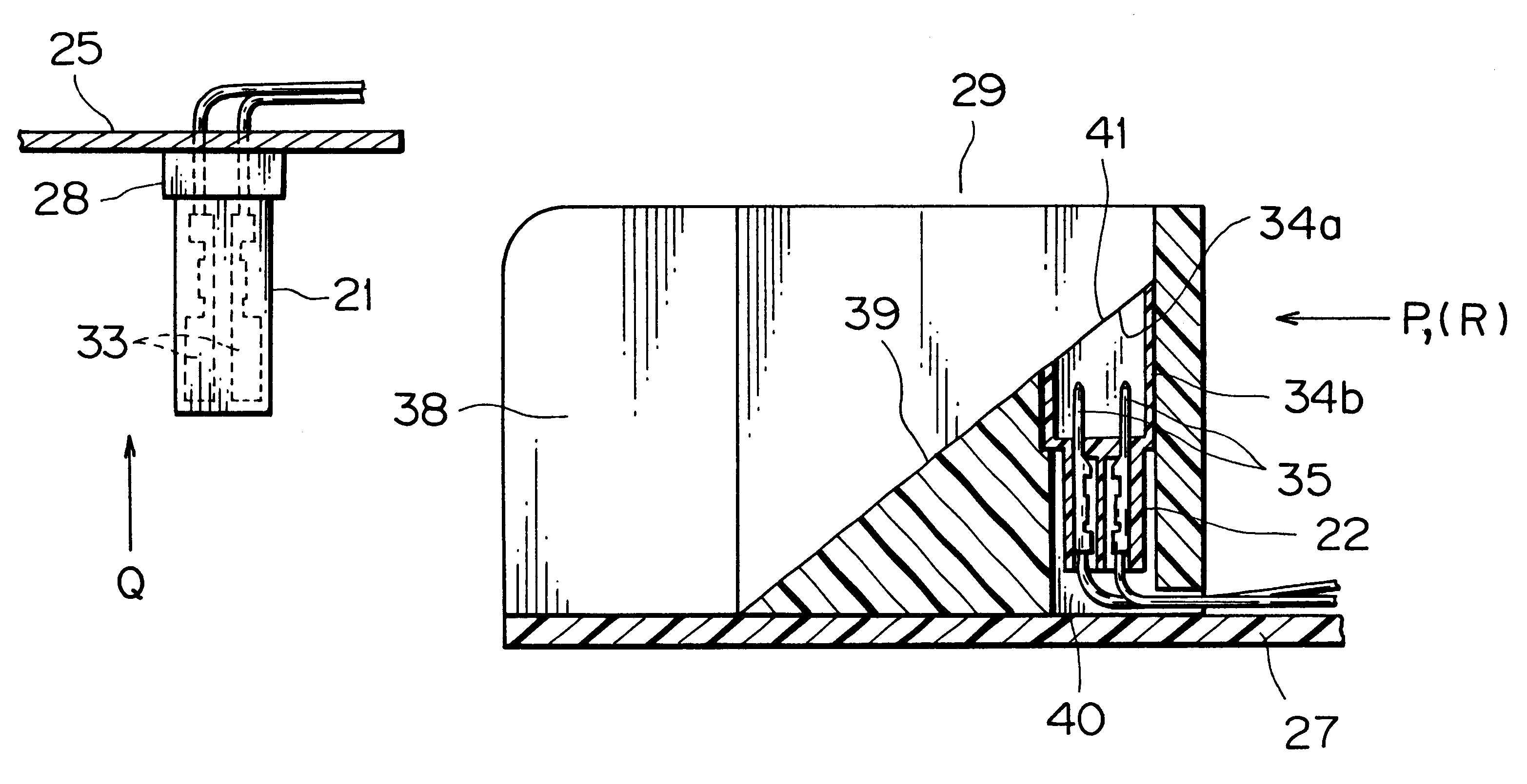
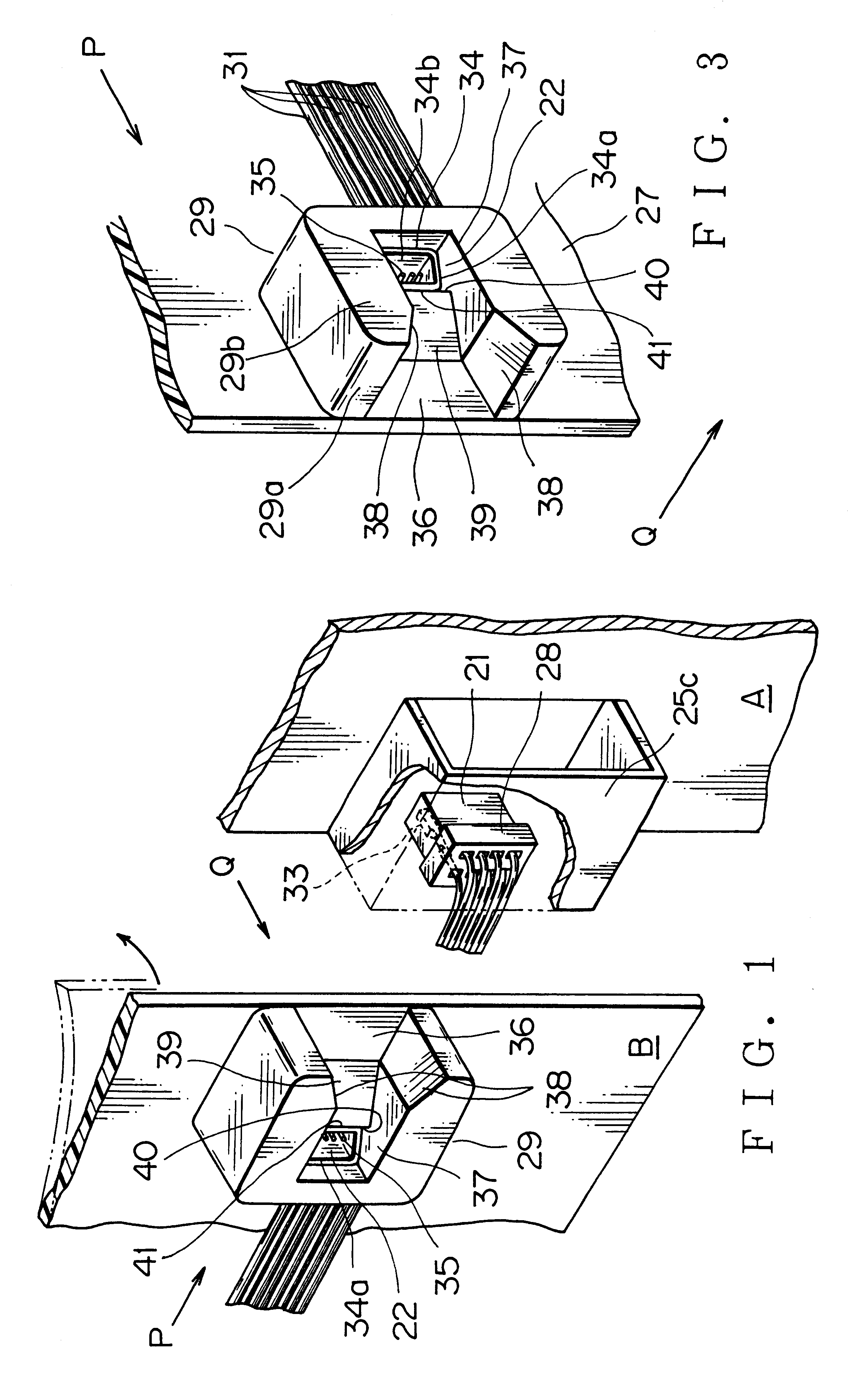
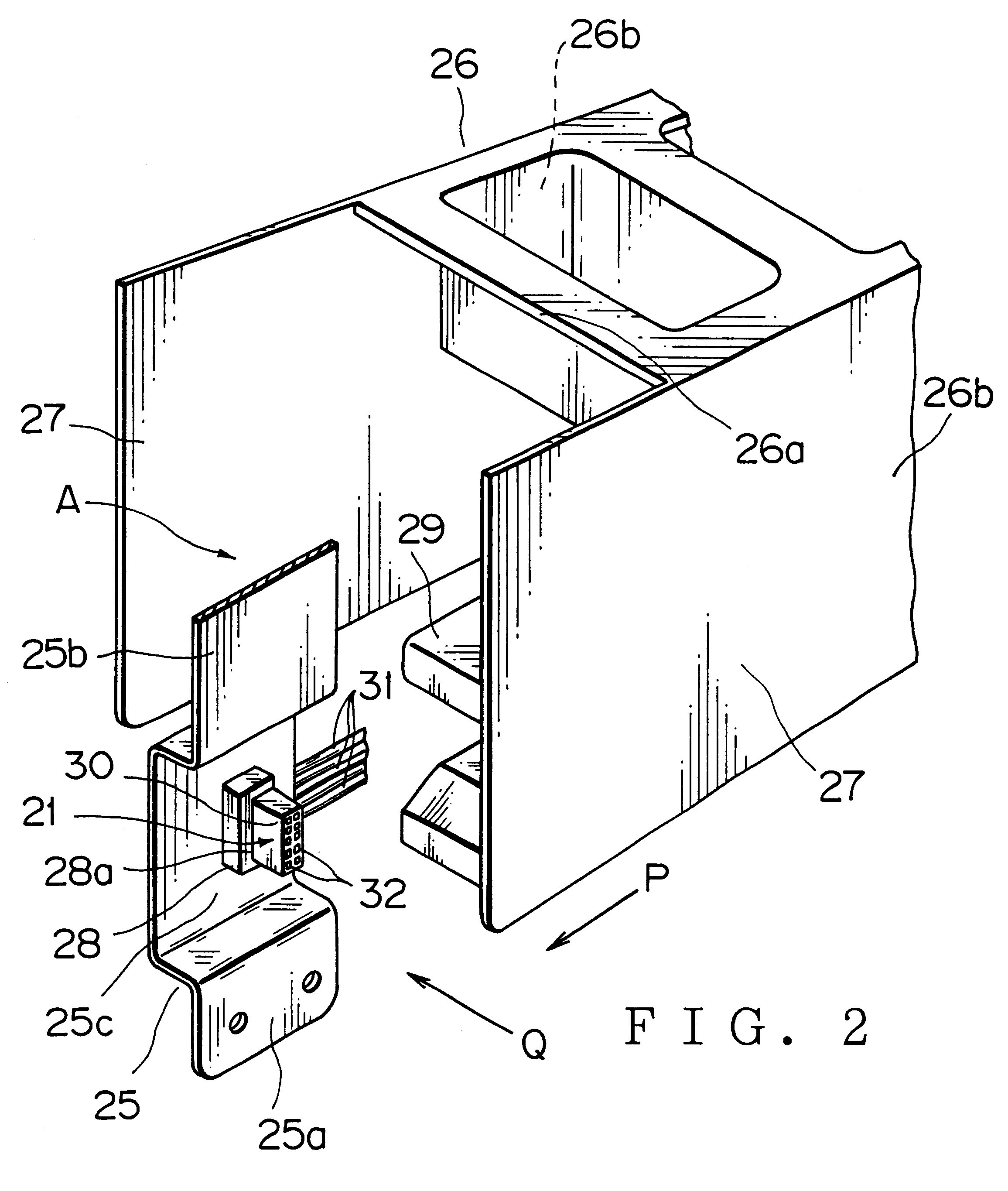
FIG. 1 is a perspective view showing a basic structure of an embodiment of a connector connecting structure according to the present invention.

As is shown in FIG. 1, the connector connecting structure according to the present invention includes a first connector 21, a second connector 22, a first mounting portion A for the first connector 21, a second mounting portion B for the second connector 22, a first connector frame 28, and a second connector frame 29 in order to make electric connection between the connectors 21,22. The first connector 21 is mounted on the first connector frame 28 which is integrally formed with or fixed to the first mounting portion A.

And, the second connector 22 is mounted on the second connector frame 29 which is integrally formed with or fixed to the second mounting portion B. The first connector frame 28 supports a wire led-out porti...


PUM


Abstract

A connector connecting structure applied to a motor vehicle is provided, which includes: a first connector having first wire connected terminals; a second connector also having second wire connected terminals and to be coupled with the first connector for making an electric connection; a first mounting portion for arranging the first connector; a second mounting portion for arranging the second connector; a first connector frame to be fixed to the first mounting portion and to support one end of the first connector so as to project the other end thereof; and a second connector frame to be fixed to the second mounting portion and including: a top-wall opening formed in a coupling direction of the first and second connectors for permitting the first connector to go through; a side-wall opening formed in a coupling operation direction of the first and second mounting portions; a slide plane, tapered or in a curve, for shifting the other end of the first connector toward the top-wall opening between the side-wall opening and the top-wall opening on coupling operation between the first and second connectors; and a connector accommodating portion provided with a receiving opening on the slide plane and directed in the coupling direction so as to receive the second connector, wherein the first and second connectors are connected with each other through the receiving opening so as to electrically connect the first and second wire connected terminals by bending at least one of the first and second mounting portions by means of sliding the other end of the first connector on the slide plane when the first and second connectors are coupled.

Description

BACKGROUND OF THE INVENTION1. Field of the InventionThe present invention generally relates to a connector connecting structure and more particularly, to a connector connecting structure which is superior in connecting workability of connectors and in positioning of connectors at coupling operation thereof.2. Description of the Related ArtFIG. 8 is a perspective view showing a conventional connector connecting structure.This connector connection structure consists of a female connector 2 fixed to an auxiliary device 1 and a male connector 4 provisionally supported by a vehicle body 3. When the auxiliary device 1 is shifted in a coupling operation direction (an arrow W direction) orthogonally to a connector coupling direction (an arrow V direction), the female connector 2 engages the male connector 4 through a slider 5.The female connector 2 is fixed to the auxiliary device 1, and a plurality of male electric terminals (not shown) each connected to an electric wire 7 are accommodated...

Claims


Application Information

Patent Timeline
IPC IPC(8): H01R13/631H01R13/629
CPCH01R13/6315H01R2201/26
Inventor DOUSHITA, KENICHI
Owner YAZAKI CORP
Learn More