
Method of operating a vehicle occupancy state sensor system

Inactive Publication Date: 2001-08-07
ROBERT BOSCH CORP
View PDF53 Cites 157 Cited by
  • Summary
  • Abstract
  • Description
  • Claims
  • Application Information

AI Technical Summary

Benefits of technology

It is an object of the present invention to provide an automotive occupancy sensor system to reliably detect the presence or absence of a passenger in the passenger seat and the presence or absence of a rear-facing child seat in the passenger seat and to provide an occupancy state signal to the air bag control system to permit it to either inhibit or deploy a passenger side air bag during a collision.
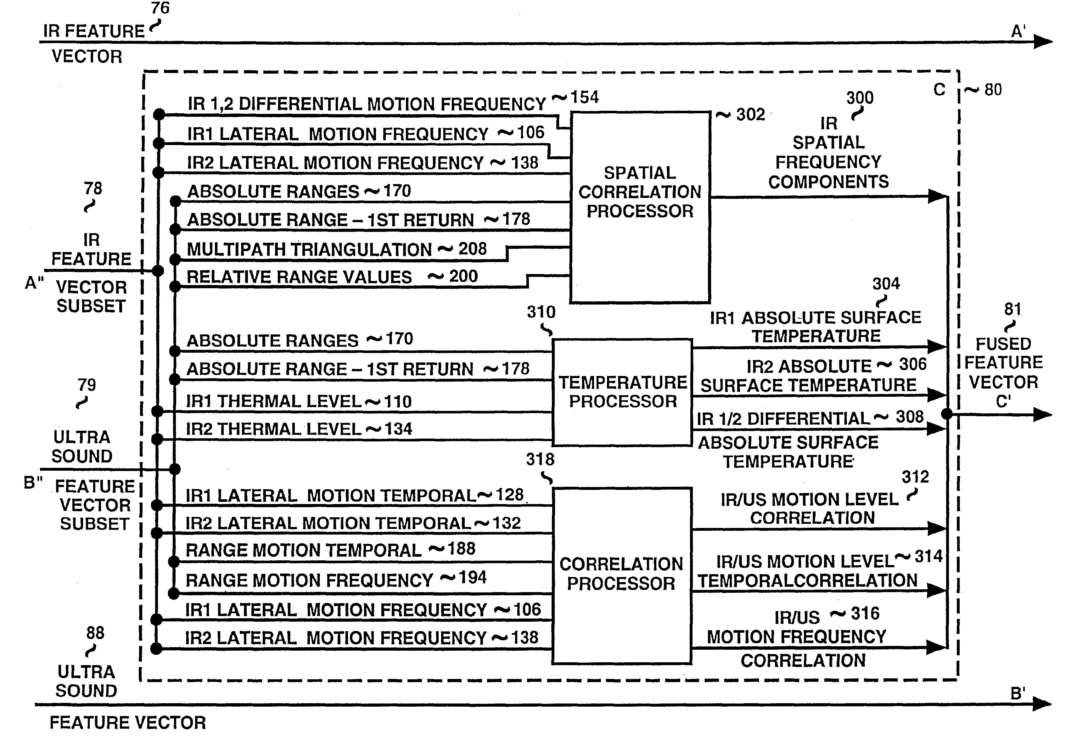
It is another object of the invention to provide a vehicle passenger sensing system which relies upon multiple sensors with cross correlation of features from different physical phenomena to provide signals which are processed by sensor fusion to significantly enhance the reliability of passenger detection while permitting the use of relatively low cost conventional sensors.
It is another object of the invention to provide a vehicle occupancy sensing system adapted for use with a passenger seat of a vehicle to control the deployment of an air bag, and specifically to provide an occupancy state signal that permits controlling, including inhibiting, the deployment of an air bag when a passenger seat is classified as unoccupied, occupied by inanimate objects, the occupant is out-of-position, or when an RICS is present in the passenger seat, in order to prevent unneeded or unsafe deployment which might otherwise cause injury.
It is another object of the invention to provide a multiple sensor occupancy detection system which processes by sensor fusion certain preselected features extracted from signals provided by different sensors which sense different physical parameters and correlate them to increase the reliability of the individual sensing characteristics of the individual sensors.
It is another object of the invention to provide a multiple sensor occupancy detection system while maintaining low cost in manufacturing of tile vehicle by locating multiple sensors co-located in a single unit to ease the task of mounting the sensor system to the vehicle.
It is another object of the present invention to provide a multiple sensor occupancy detection system while maintaining aesthetics of the vehicle by producing a sensor system of minimal size.

Problems solved by technology

However, a passenger-side air bag deployment system presents problems in regard to criteria for deployment.
That is, it is not simply an issue of always deploying a passenger air bag, as injury to occupants can occur by deployment in certain situations.
An even more important problem is the danger of deploying a passenger side air bag when it has a rear-facing child seat (RFCS).
The deployment of an air bag against the back portion of an RFCS occupied by a child can cause serious injury to the child by catapulting the child into the back of the car seat, thus defeating the safety advantages of both the air bag and the RFCS during a collision.
Thus, it is no easy task to provide a sensor system, meaning sensor units and methods of operation and signal processing, to reliably detect change of state from an empty to an occupied seat and determine the nature (classify), position (location) and / or orientation of an object or passenger in the vehicle.
Thus, a thermal sensor acting alone can lead to falsely declared occupant presence, and more importantly, failure to detect the presence of an occupant.
Furthermore, the cost of installing such system in the vehicle must remain simple to keep manufacturing cost low.
There is no currently available sensor system known to the Applicants which can reliably distinguish the presence, absence and nature of an object or a passenger in the passenger seat.
None today can selectively distinguish the presence or absence of a rear-facing child seat in the passenger seat.
There is also no currently available sensor system that can account for a wide variety of possible variations in both thermal and distance parameters that are encountered in the actual wide range of circumstances of occupancy, nor one that is sufficiently versatile to be adaptable to the wide range of vehicle interior configurations.

Method used


Image

  • Method of operating a vehicle occupancy state sensor system
  • Method of operating a vehicle occupancy state sensor system
  • Method of operating a vehicle occupancy state sensor system

Examples


Embodiment Construction

and Claims.

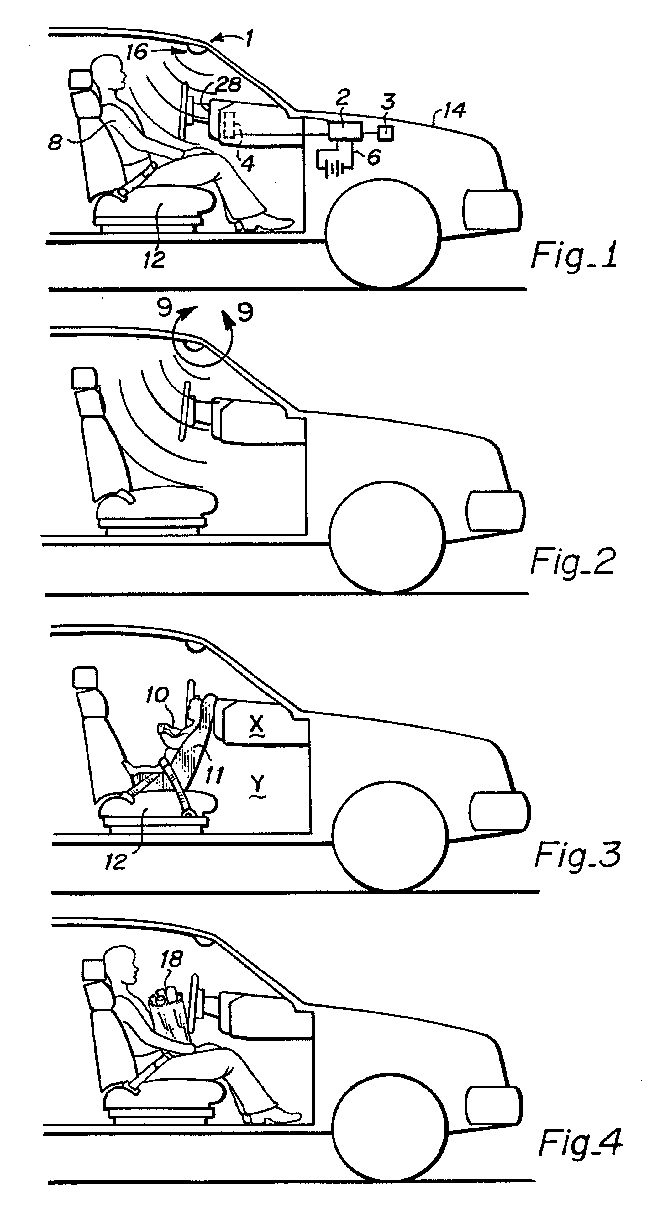
The invention is illustrated in the drawings in which:

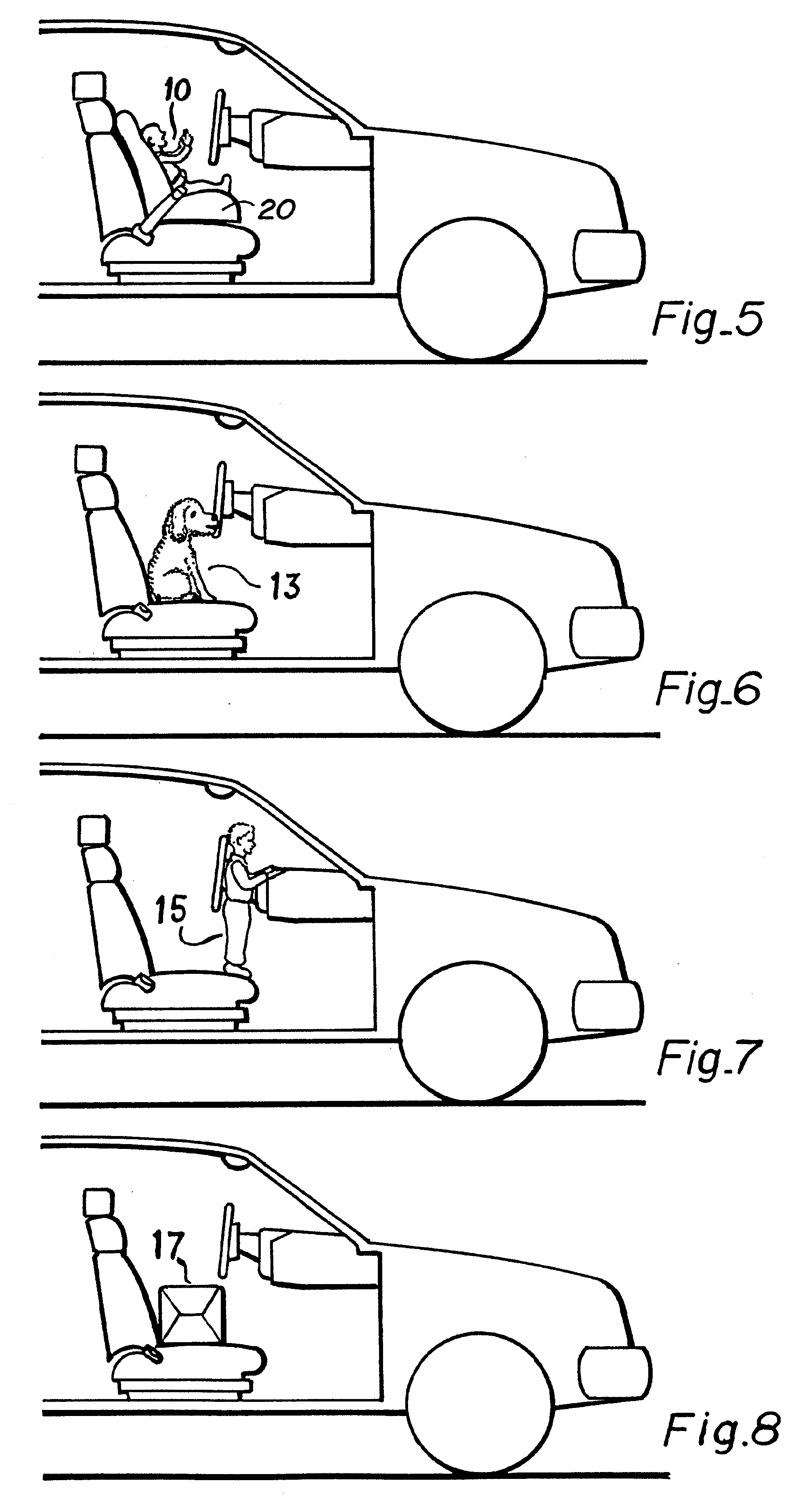
FIGS. 1-8 show various conditions illustrative of some of the variety and range of real conditions that must be detected and accurately discriminated-amongst (classified) by a fully-functional automotive occupant sensor system which, by way of example, is focused on a passenger seat of a vehicle, with:

FIG. 1 showing the seat being occupied by a passenger;

FIG. 2 showing the passenger seat unoccupied and sensed as "empty";

FIG. 3 showing a child in a rear-facing child seat ("RFCS");

FIG. 4 showing a passenger holding a bag of groceries;

FIG. 5 showing a child in a forward-facing child seat ("FFCS");

FIG. 6 showing a dog in the seat;

FIG. 7 showing an out-of-position passenger ("OOP"); and

FIG. 8 showing a moderate sized package on the seat;

FIG. 9A is an enlarged front view of the sensor taken along line 9--9 of FIG. 2 having a multi-element infrared sensor and an ultrasound sensor contained in a single unit, and illustrating a...


PUM


Abstract

A system for sensing the presence, position and type classification of an occupant in a passenger seat of a vehicle, as well as for sensing the presence of a rear-facing child seat therein, for use in controlling a related air bag activator control system to enable, disable or control inflation rate or amount of inflation of an air bag. The sensor system employs sensor fusion, a process of combining information provided by two or more sensors (24, 26), each of which "sees" the world in a unique sense. In a preferred embodiment, infrared sensor inputs (78) and ultrasonic sensor inputs (79) are combined in a microprocessor by a sensor fusion algorithm (80) to produce an occupancy state output signal (85) to the air bag controller.

Description

FIELDThis invention relates to automotive occupancy sensor (AOS) systems and methods of operation by sensor fusion to determine the presence and position of an object in a seat, and to classify it by type or nature, to provide an occupancy state or condition signal for use with other automotive control systems, typically in conjunction with air bag activation or other type of safety restraint system for protection of passengers in the event of a collision. A principal embodiment is a multi-sensor US / IR occupant detection unit co-located in the vehicle headliner which provides an occupancy state signal to an air bag controller. The AOS determines by fusion of cross correlated sensor features the presence, absence, orientation and classification of a human or animal occupant, child seat (front or rear-facing), out-of-position occupant, or other types of occupancy, to provide an occupancy state signal to the air bag controller which indicates the appropriateness to deploy (or not) the ...

Claims


Application Information

Patent Timeline
IPC IPC(8): B60N2/00B60R21/01G01S15/04G01S15/02G01S15/52G01S15/00G06K9/00G06K9/68G01S15/88G01S7/539G01S7/523G01S7/526B60R21/16B60R21/015G06K9/62
CPCB60N2/002G01S15/025G01S15/04G01S15/523B60R21/0154G06K9/00362G06K9/6293B60R21/01536B60R21/01532B60R21/01534G01S7/526G01S7/539G01S15/88G01S15/86G06V40/10G06V10/803G06V20/593G06V10/147B60R21/015B60R21/01B60R21/16B60R21/261G06F18/256
Inventor CORRADO, ANTHONY P.DECKER, STEPHEN W.BENBOW, PAUL K.
Owner ROBERT BOSCH CORP
Learn More