Pneumatic-hydraulic rivet gun

a pneumatic-hydraulic and rivet gun technology, applied in the direction of metal-working equipment, portable power tools, metal-working equipment, etc., can solve the problems of poor efficiency right when a very high torque, difficult and scarce use of rivet guns, and small torques

Inactive Publication Date: 2001-08-14
OBER UTENSILI PNEUMATICI
View PDF9 Cites 60 Cited by
  • Summary
  • Abstract
  • Description
  • Claims
  • Application Information

AI Technical Summary

Problems solved by technology

It is clear enough that, with such constructive configuration, reverse rotation, or counter-clockwise rotation, of the pneumatic engine cannot be efficient and the resulting torque is rather small.
The rivet guns like the one described hereinabove, have some drawbacks which make their use difficult and scarcely efficient.
First of all, this technique used to reverse the rotation of the pneumatic engine makes it poorly efficient right when a very high torque would be necessary, i.e. when the tip of the rivet holding stem must be extracted from the rivet.
In fact, when the rivet is buckled, the internal thread becomes damaged and anyway does no longer extend in a perfect line.
This solution actually improves the effectiveness of the rivet gun, but the screwing step becomes often difficult and slow, so that the problem cannot be said to be c

Method used


Image

  • Pneumatic-hydraulic rivet gun
  • Pneumatic-hydraulic rivet gun
  • Pneumatic-hydraulic rivet gun

Examples


Embodiment Construction

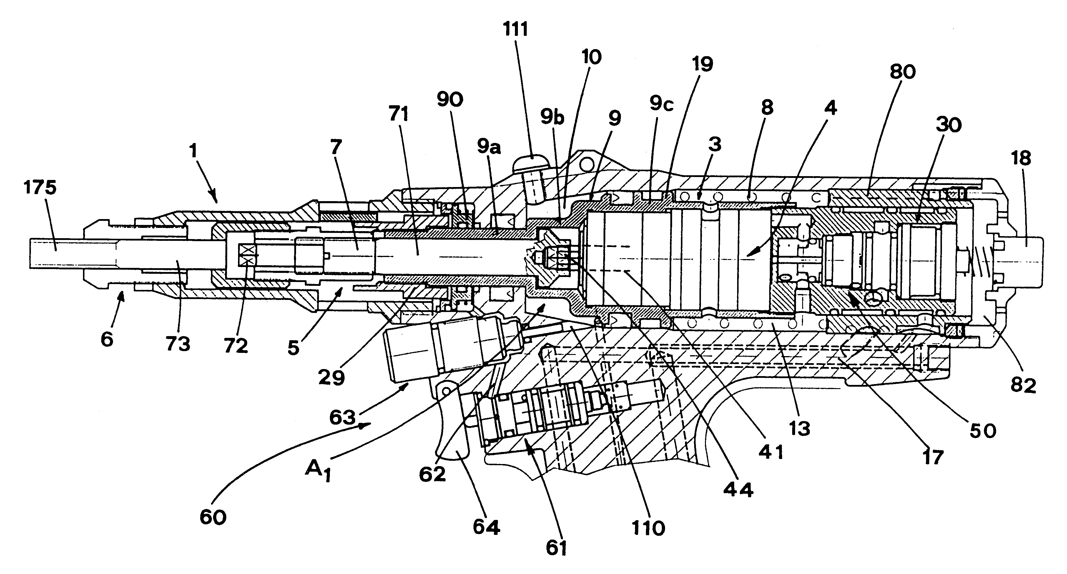
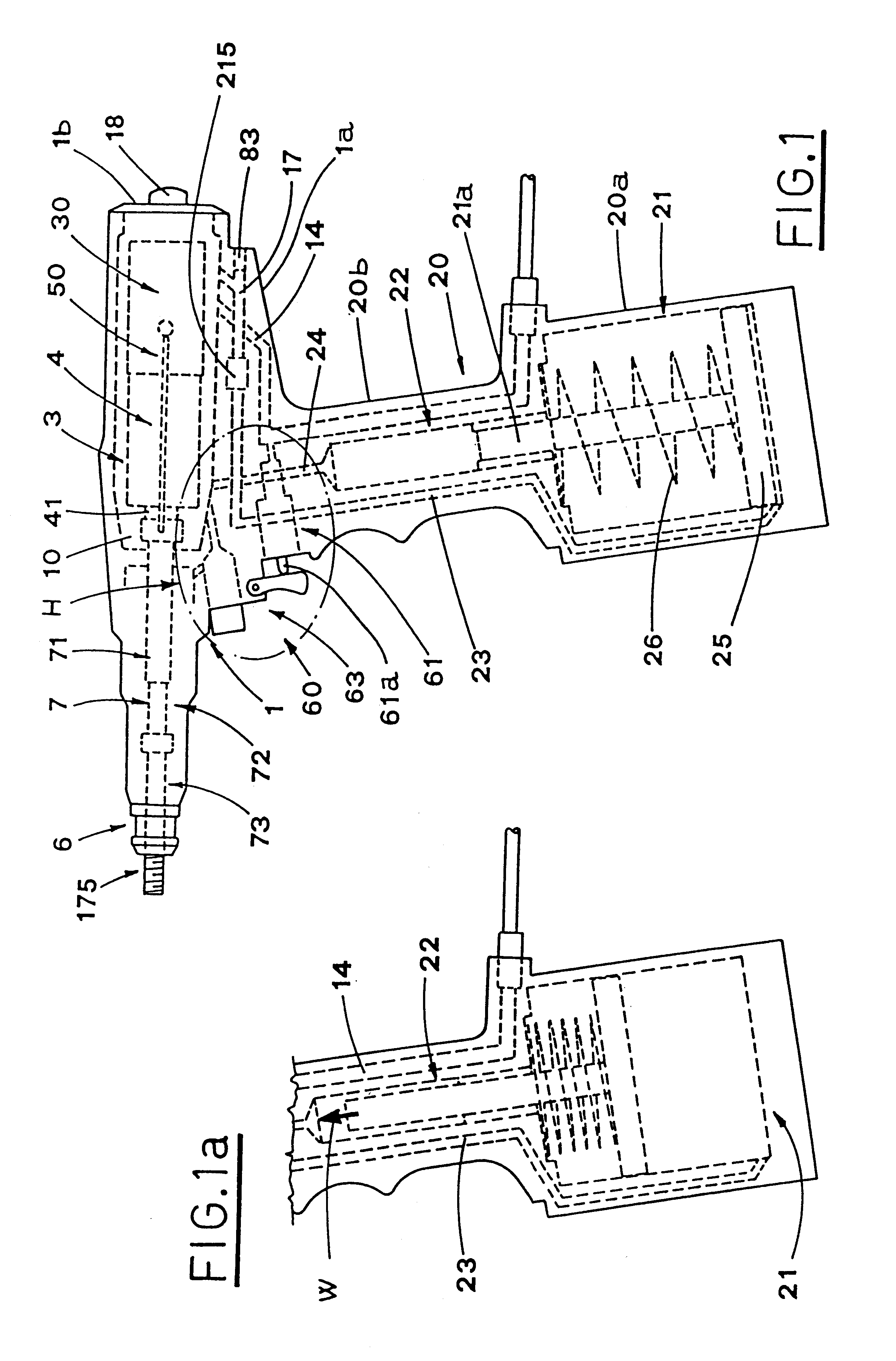
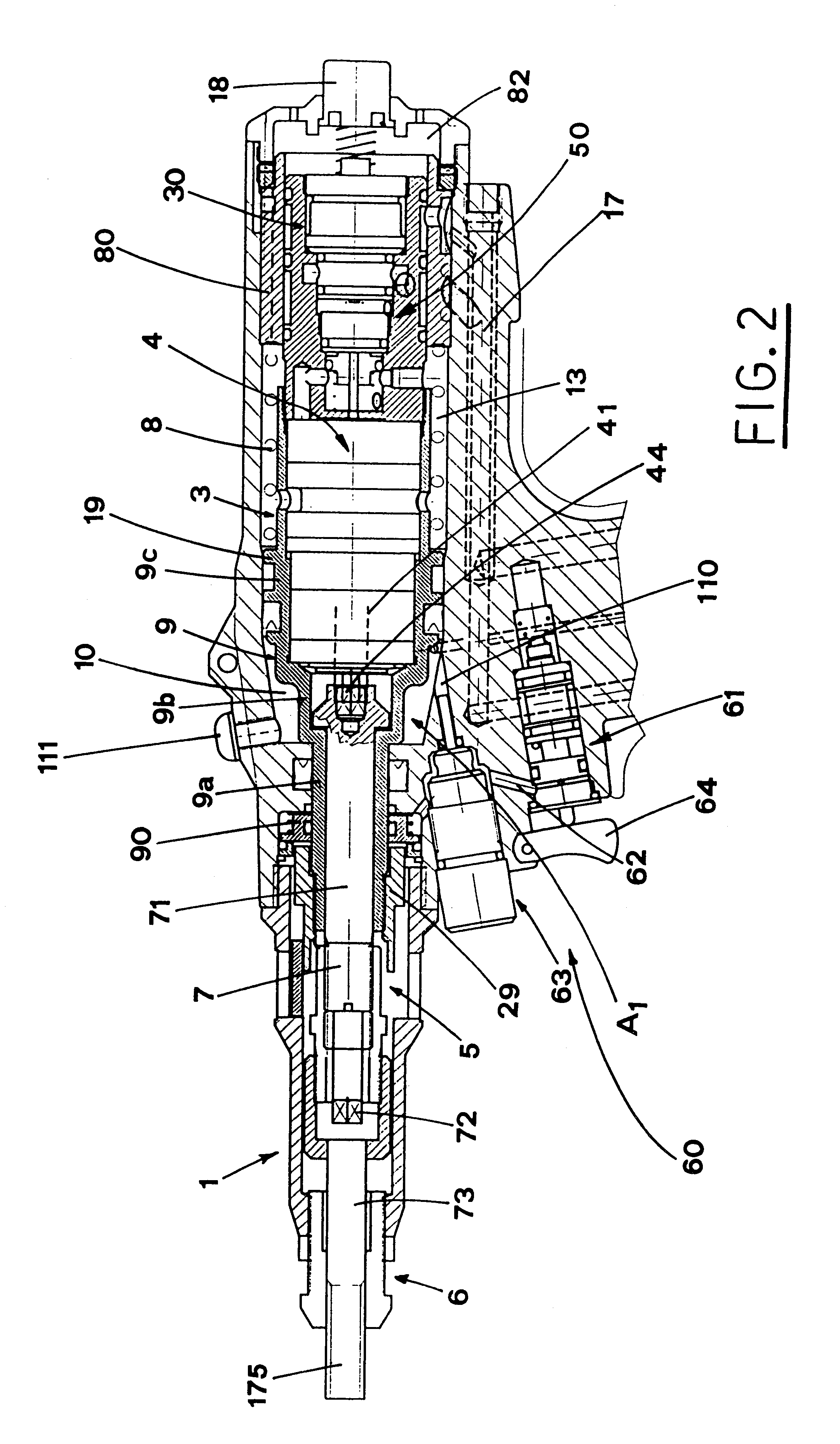
With reference to FIGS. 1 and 2, numeral 1 indicates the casing of a rivet gun manufactured according to the present invention. The casing is preferably made of metal or other suitable material.

This casing has an elongated shape and is formed by portions with gradually decreasing diameters, beginning from a rear end 1b up to the fore end 6.

A hollow handle 20 extends downwards from the lower side 1a of the casing 1, approximately from its middle part

The inner part of the casing 1 features a rear shaped cavity 3 and a fore channel 5 substantially cylindrical. The rear cavity 3 and the fore channel 5 are aligned along a casing longitudinal middle axis.

The rear cavity 3 takes the whole of the rear part of the casing 1 and communicates with outside through suitable holes, not shown, made in the casing 1.

The rear part of the fore channel 5, that is located in the fore part of the casing 1, communicates with the cavity 3, while its fore part opens outward in the region of the fore end 6 of...


PUM

PropertyMeasurementUnit
Forceaaaaaaaaaa
Pressureaaaaaaaaaa
Flow rateaaaaaaaaaa

Abstract

A rivet gun includes a pneumatic motor (4), that drives a segment stem 7. A pneumatic cylinder (21) actuates a hydraulic cylinder (22) which sends oil under pressure to an expansion chamber (10) provided for moving back the segment stem (7) and buckling the rivet (2) fixing it to a laminate structure (100). The rivet gun also includes a change-over switching device (30) linked to controls (50,60) for reversing rotation of the motor (4). The controls (60) include an inlet valve (61) operated by a trigger (64) for connecting a compressed air infeed duct 14 with a feed-discharge duct (23) leading to the pneumatic cylinder (21). A discharge valve (63) is disposed in series with the inlet valve (61) and has an adjustment ring (176) for adjusting of the maximum traction force. Another discharge valve (90) is disposed in series with the discharge valve (63) previously mentioned and is provided for adjustment of the stroke of the segment stem (7).

Description

1. Field of the InventionThe present invention relates to the technical field concerned with the production of hydraulic, pneumatic, or pneumatic-hydraulic tools.In particular, the present invention concerns a rivet gun operated by pneumatic-hydraulic means.The rivet gun is designed for application of rivets provided with an internal thread.2. Prior ArtIt is known that rivets are usually fixed to laminate structures, basically including pieces of rigid sheet made from metal or other suitable materials.Suitable tools, preferably operated by pneumatic or pneumatic-hydraulic means, are used for fixing the rivets to the laminate structure. These tools take usually the shape of a gun, so that they can be easily handled by an operator who has to apply the rivets to the internal thread.Among various constructive and operative configurations, the one which uses pneumatic-hydraulic means has resulted to be the most effective, reliable and cheap.Basically, known rivet guns include each one a ...

Claims


Application Information

Patent Timeline
IPC IPC(8): B25B27/00B21J15/06B25F5/00
CPCB25B27/0014Y10T29/53752Y10T29/53748
Inventor BENTIVOGLI, NERIO
Owner OBER UTENSILI PNEUMATICI
Why Eureka
Try Eureka