Downhole tractor

a tractor and downhole technology, applied in the field of downhole tools, can solve the problems of more complex situation, exceeding 500 tons, and imposing downward axial thrus

Inactive Publication Date: 2001-08-14
HALLIBURTON ENERGY SERVICES INC
View PDF26 Cites 298 Cited by
  • Summary
  • Abstract
  • Description
  • Claims
  • Application Information

AI Technical Summary

Problems solved by technology

For pipe strings in relatively deep wells, this downward axial thrust can be quite formidable, sometimes exceeding 500 tons.
The situation is more complex in highly deviated and horizontal wells.
However, in most deviated well situations, the string will drag against the walls of the well bore at some point below the commencement of the deviated portion of the well.
The relatively small outer diameters and wall thicknesses of coiled tubing place severe limits on the amount of surface-supplied downward thrust that can be applied to a coiled tubing string without buckling the tubing.
Retrieval of pipe and coiled tubing strings, and wireline assemblies is also more complex in deviated and horizontal wells.
Coiled tubing strings and wireline assemblies are more problematic in that their capacity to withstand tensile loads can be quite limited, particularly for wireline assemblies.
If the tensile limit of a coiled tubing string or wireline assembly is exceeded, a costly fishing operation may be required to clear the wellbore.
One disadvantage common to many conventional designs is the lack of redundancy in power output to the propulsion wheels.
The difficulty with such designs is that power failure in the single drive motor results in loss of power to all of the drive wheels.
Another disadvantage of such conventional designs is the sheer complexity of the mechanical leakages between the drive wheels and the common power motor.
Another disadvantage common to some conventional tractor designs is the inability to provide axial movement in both directions.
Such fine tuning of the position of the logging tool relative to the bore hole can be extremely difficult if the propulsion apparatus is limited to a single direction of travel.
Crawler type propulsion tools have the disadvantages of relatively slow travel speed and sometimes jerky longitudinal movements downhole.
The relatively slow travel speeds of crawler type propulsion systems is a natural, though undesirable by-product of the reciprocating type of movement associated with the traction members of such devices.
That very reciprocating type of movement also can lead to abrupt and jerky movements of the string downhole.
Slow insertion and retrieval often translates into higher operating costs for the operator.

Method used


Image

  • Downhole tractor
  • Downhole tractor
  • Downhole tractor

Examples


Embodiment Construction

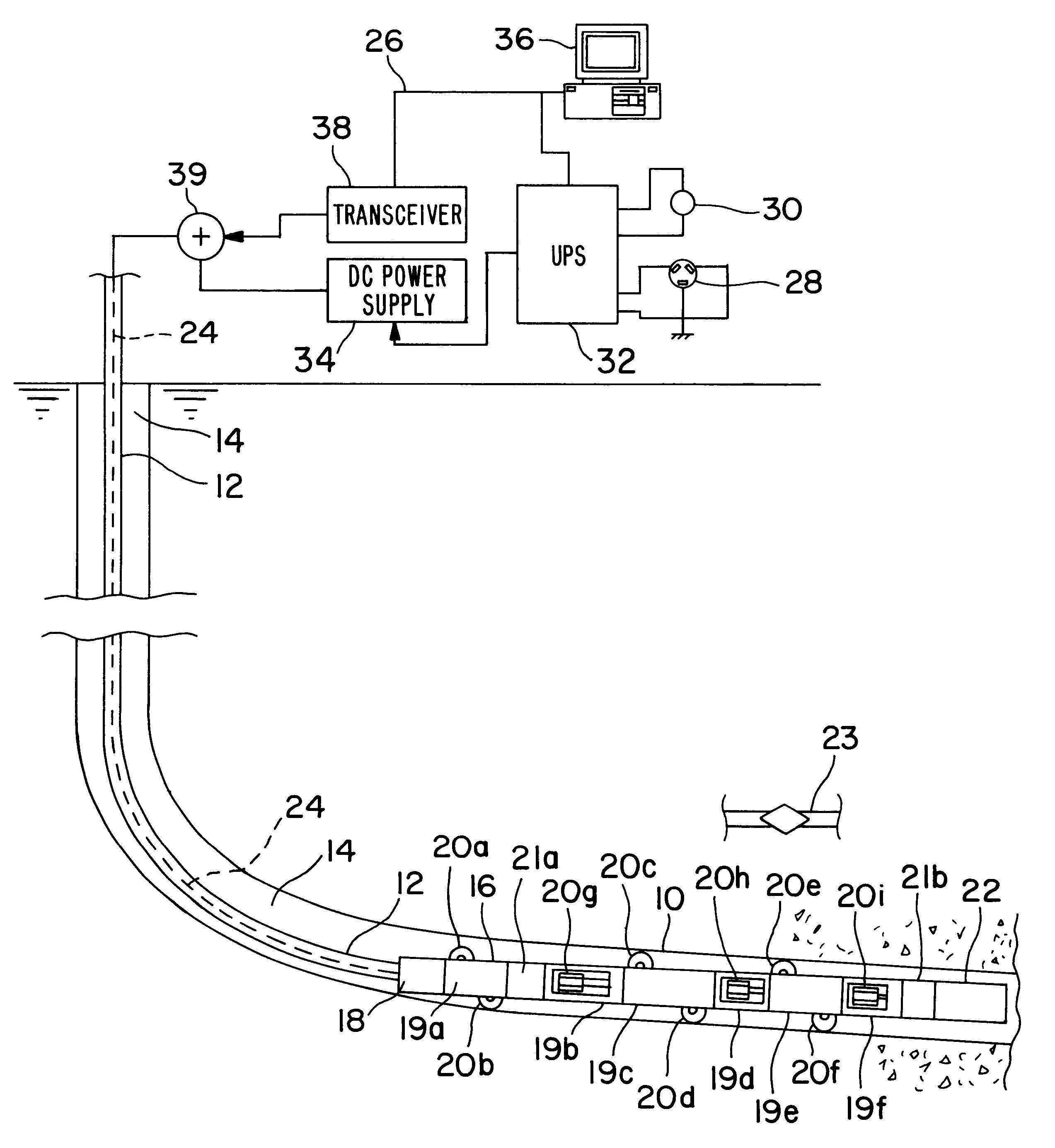
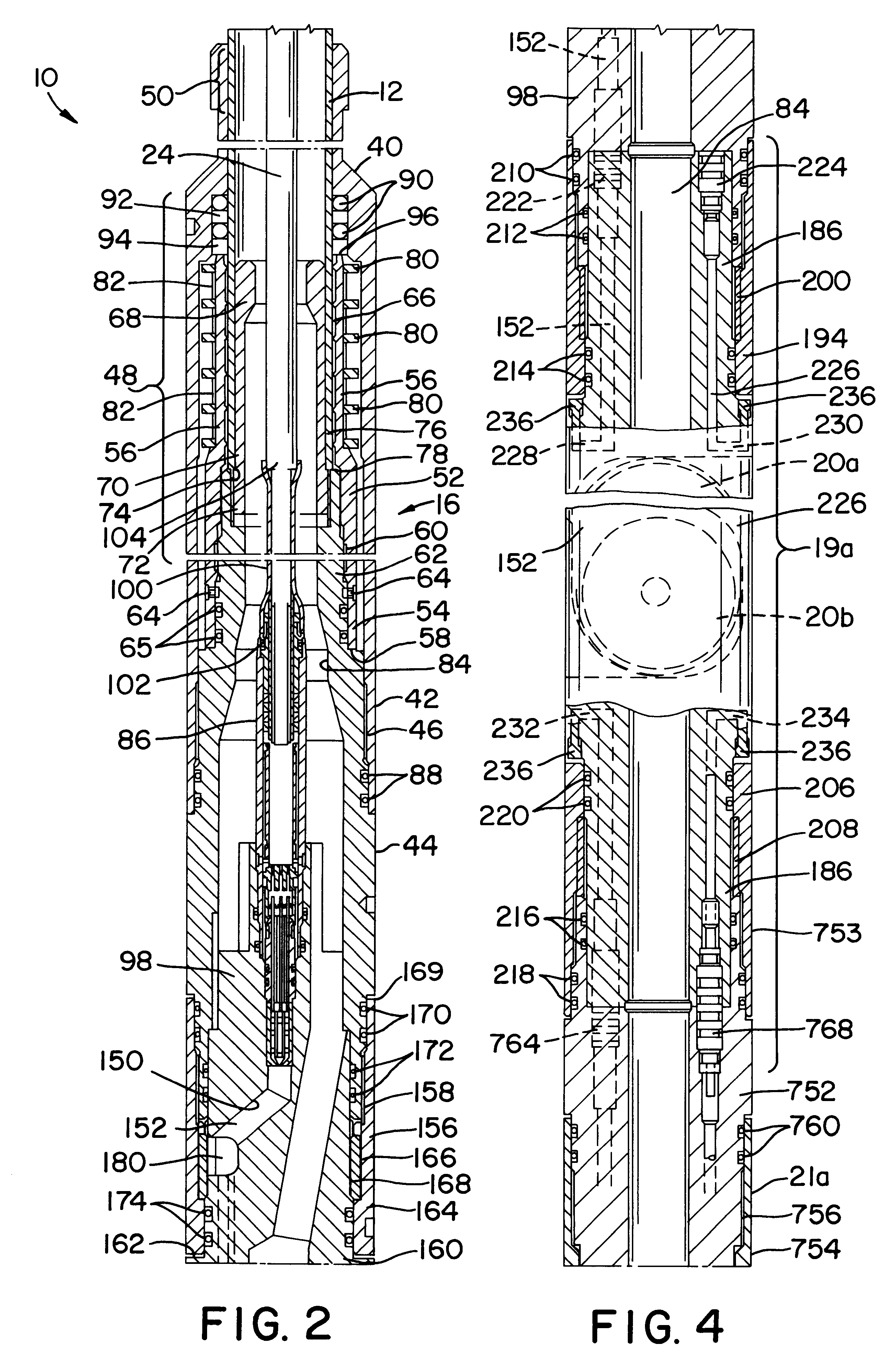
Turning now to the drawings, and in particular to FIG. 1, there is shown an exemplary embodiment of a downhole tractor 10 coupled to a length of coiled tubing 12 and positioned in a deviated wellbore 14. The wellbore 14 may be a cased well, a working string or an open hole, and is of such length that it is shown broken. The downhole tractor 10 includes a tubular housing 16 that is subdivided into various subs. A coupling sub 18 is connected to the tubing 12. A total of six powered wheel modules or subs 19a, 19b, 19c, 19d, 19e and 19f are coupled to the coupling sub 18. Each of the wheel subs 19a, 19b, 19c, 19d, 19e and 19f includes two powered wheel assemblies for propelling the downhole tractor 10. The illustrated embodiment of the downhole tractor 10 includes twelve wheel assemblies. Nine of the wheel assemblies are designated, respectively, 20a, 20b, 20c, 20d, 20e, 20f, 20g, 20h and 20i. Three others are not visible in FIG. 1. Two of the wheel assemblies that are not visible are ...


PUM


Abstract

A downhole tractor is provided that includes a housing and a first wheel assembly coupled to the housing that is operable to translate away from the housing in a first direction. The first wheel assembly has a first electric motor, a first wheel, and a first reduction gear assembly coupled between the first electric motor and the first wheel. A second wheel assembly is coupled to the housing and is operable to translate away from the housing in a second direction that is opposite to the first direction. The second wheel assembly has a second electric motor, a second wheel, and a second reduction gear assembly coupled between the second electric motor and the second wheel. A fluid ram is coupled to the first and second wheel assemblies for selectively translating the first and second wheel assemblies toward and away from the housing. A first controller is provided for controlling the flow of current to the first and second electric motors. On-board and surface control systems may be incorporated to permit selective active of the wheels assemblies. In addition, couplings and connectors employing shape-memory materials may be included to secure the tractor to coiled tubing or a wireline.

Description

1. Field of the InventionThis invention relates generally to downhole tools, and more particularly to a downhole tractor for propelling working strings and wirelines in a wellbore.2. Description of the Related ArtSubterranean operations in petroleum wells involve the conveyance of pipe, coiled tubing and wireline supported tools from the surface into well bores and vice versa. In vertical wells, and in those wells having only a few degrees of deviation, the axial thrust necessary to convey pipe or coiled tubing strings, or wireline tools, is supplied by gravity. In these situations, the downward thrust applied to the string is equal to the weight of the drill string, minus any buoyancy force due to fluid downhole. For pipe strings in relatively deep wells, this downward axial thrust can be quite formidable, sometimes exceeding 500 tons. Although the weight of a conventional coiled tubing string will be significantly less than a comparably sized drill pipe string, additional axial do...

Claims


Application Information

Patent Timeline
Patent Type & Authority Patents(United States)
IPC IPC(8): E21B23/00E21B4/18E21B4/00
CPCE21B4/04E21B4/18E21B23/14E21B23/00E21B2023/008E21B23/001
Inventor GISSLER, ROBERT W.HOLCOMBE, MICHAEL W.PURKIS, DANIEL
Owner HALLIBURTON ENERGY SERVICES INC
Why Eureka
Try Eureka