
Frame piece for a rack for a switching cabinet

a technology for switching cabinets and frame pieces, applied in the direction of substation/switching arrangement casings, other domestic objects, show shelves, etc., can solve the problems of not offering satisfactory solutions in all respects, and the design of frame pieces designed as open hollow profile sections is considerably worse than closed hollow profile sections

Inactive Publication Date: 2001-08-14
RITTALWERK RUDOLF LOH GMBH & CO KG
View PDF6 Cites 25 Cited by
  • Summary
  • Abstract
  • Description
  • Claims
  • Application Information

AI Technical Summary

Benefits of technology

The free space to the outside corner edge delineated by the profile sides of the profile outside offers sufficient clearance for swinging a cabinet door as well as to introduce beveled paneling elements at the frame piece. The sealing struts, connecting struts and / or receiving grooves in the connecting struts of the profile outside offer many possible variations. The closed hollow profile of the frame piece with one or two hollow spaces has very good stability, especially deformation strength, which can also be used to minimize the material expenditure for the frame piece, especially when the frame piece is stamped from a strip, is bent and is assembled.
The frame piece can be easily produced as a section of an extruded profile.

Problems solved by technology

Many frame pieces are known for the rack of a switching cabinet, which partly fulfill the requirements named above, but do not offer satisfactory solution in all respects.
Frame pieces designed as open hollow profile sections are considerably worse than closed hollow profile sections.

Method used


Image

  • Frame piece for a rack for a switching cabinet
  • Frame piece for a rack for a switching cabinet
  • Frame piece for a rack for a switching cabinet

Examples


Embodiment Construction

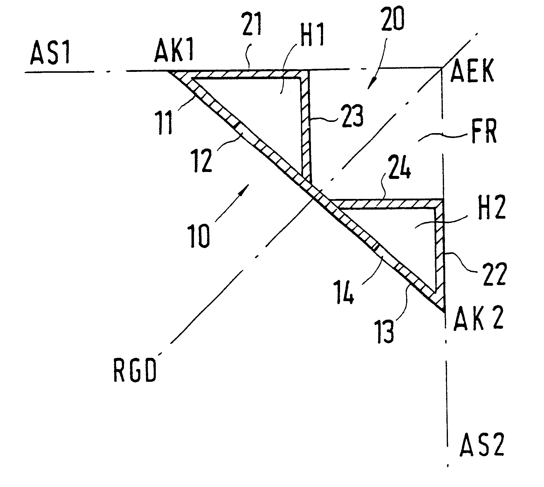
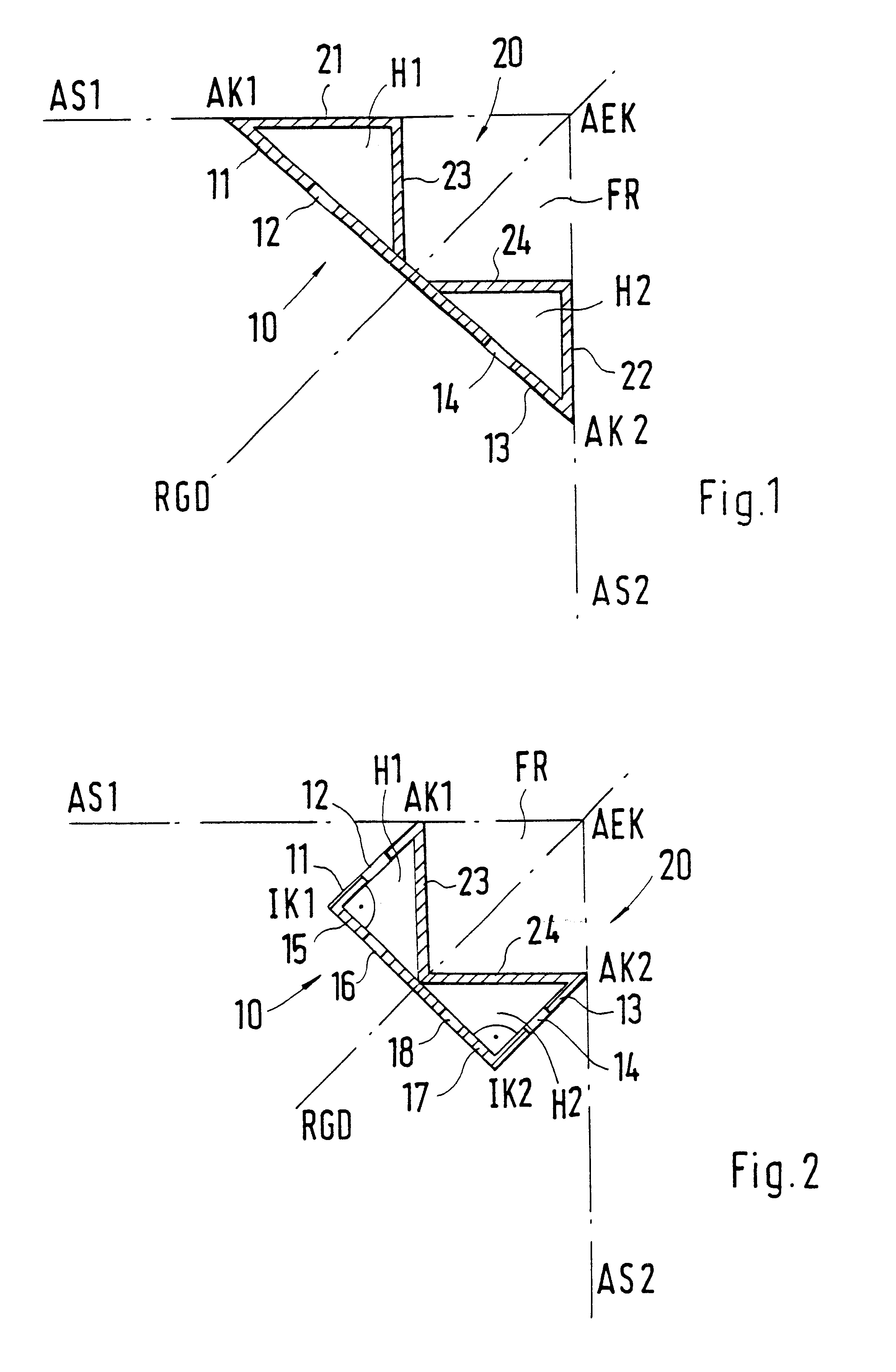
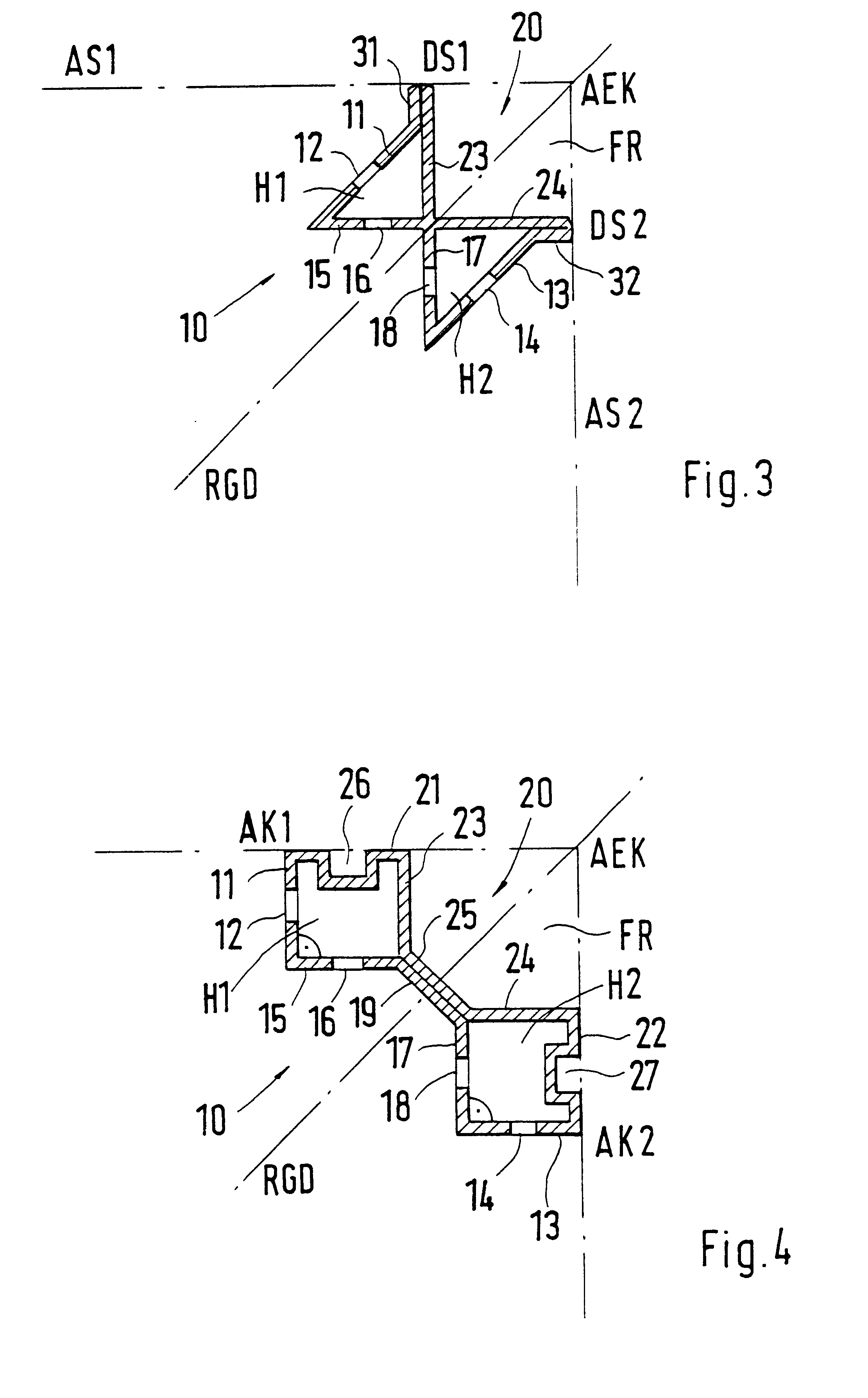
In all practical examples, AS1 and AS2 designate the two outsides of a rack meeting at a right angle, and the rack diagonal RGD is shown as the angle bisector. The two outsides, AS1 and AS2, form an outside corner edge AEK, but this does not adversely affect the frame piece with its profile outside 20 and allows sufficient free space FR. The profile outside 20 and the profile inside 10 are, however, preferably, not necessarily arranged in a mirror-image manner to the diagonal of the rack RGD and form outside edges AK1 and AK2 on outsides AS1 and AS2. If the profile inside 10 and the profile outside 20 are outside outer edges AK1 and AK2, preferably, connected to one another in the region of the rack diagonal RGD, then the frame piece encloses two hollow spaces H1 and H2, which can be designed so that they have a cross-section as right-angled isoceles or right-angled equilateral triangles, as shown in the practical examples according to FIGS. 1 to 3. The hollow spaces H1 and H2 may a...


PUM


Abstract

A frame piece for a rack of a switching cabinet. With minimum material an optimum result is obtained with regard to fastening planes and fastening direction as well as stability. A profile inside and a profile outside are used to form the frame piece as a closed hollow profile with one or two longitudinally directed hollow spaces. The profile outside delineates a free space to an outside corner edge of the rack. The profile inside has a profile section with several rows of fastening seats or several profile sections at an angle with respect to one another with at least one series of fastening seats. The profile inside and the profile outside form outside edges in a region of the right-angled abutting outsides of the rack. The outside edges are designed as double-layer sealing struts or connected to them in a direction to the outside corner edge connecting struts with or without receiving grooves for sealing elements.

Description

1. Field of the InventionThis invention relates to a frame piece for a switching cabinet.2. Description of Prior ArtGreatly varied requirements are set for a rack for a switching cabinet and these requirements must be fulfilled by all the cross-sectional shapes of the frame pieces used. In an area of the bottom frame or the top frame, one can use frame pieces which have a cross-sectional form different from the vertical frame piece. Especially for the frame pieces which are in the vertical direction of the rack, as many fastening possibilities as possible are required in several directions. Moreover, with as low material expenditure for the frame piece as possible, optimum strength, preferably strength to deformation, and yet simple manufacture of the frame piece should be possible. Moreover, in the region of the vertical outside corner edges of the rack, sufficient free space should be available to apply the hinge for a cabinet door and to form an introduced sealing element for the...

Claims


Application Information

Patent Timeline
Patent Type & Authority Patents(United States)
IPC IPC(8): H02B1/01H02B1/00H05K7/18H02B1/30H02B3/00
CPCH02B1/01H02B1/013
Inventor NICOLAI, WALTERMUNCH, UDOVOGEL, GEORG
Owner RITTALWERK RUDOLF LOH GMBH & CO KG
Learn More