Apparatus and method for controlling a rated system pressure

a technology of rated system pressure and apparatus, which is applied in the direction of fluid pressure control, gas/liquid distribution and storage, water mains, etc., can solve the problems of changing the rated system pressure, large error or fault source, damage to system components or pressure-driven devices connected to the system

Inactive Publication Date: 2001-08-14
A ROMHELD
View PDF7 Cites 62 Cited by
  • Summary
  • Abstract
  • Description
  • Claims
  • Application Information

AI Technical Summary

Benefits of technology

FIG. 1 is a block diagram of the elements of a hydraulic system including the pressure control system of the invention; and
FIG. 2 is a cross-sectional view through the present pressure control system with two valves and a pressure sensor in a common housing.

Problems solved by technology

Changing the rated system pressure, however, introduces a relatively large source of error or fault, since at least two elements that influence each other must be adjusted.
Even minor errors in the adjustment can result in damage to system components or to pressure-driven devices connected to the system, such as workpiece holding clamps.
In addition, the pressure switch functions imprecisely in the lower pressure range and with a large hysteresis.
Consequently, adjusting the system pressure can be problematic in many cases.
The disadvantage of such an arrangement is that a mechanical adjustment across greater pressure ranges is often inaccurate since the spring forces of the elements, i.e. in the pressure relief valve and in the pressure switch, differ.
As a result, differential forces flow into the mechanics, thus making it quite difficult and time-consuming to achieve an exact adjustment.

Method used


Image

  • Apparatus and method for controlling a rated system pressure
  • Apparatus and method for controlling a rated system pressure
  • Apparatus and method for controlling a rated system pressure

Examples


Embodiment Construction

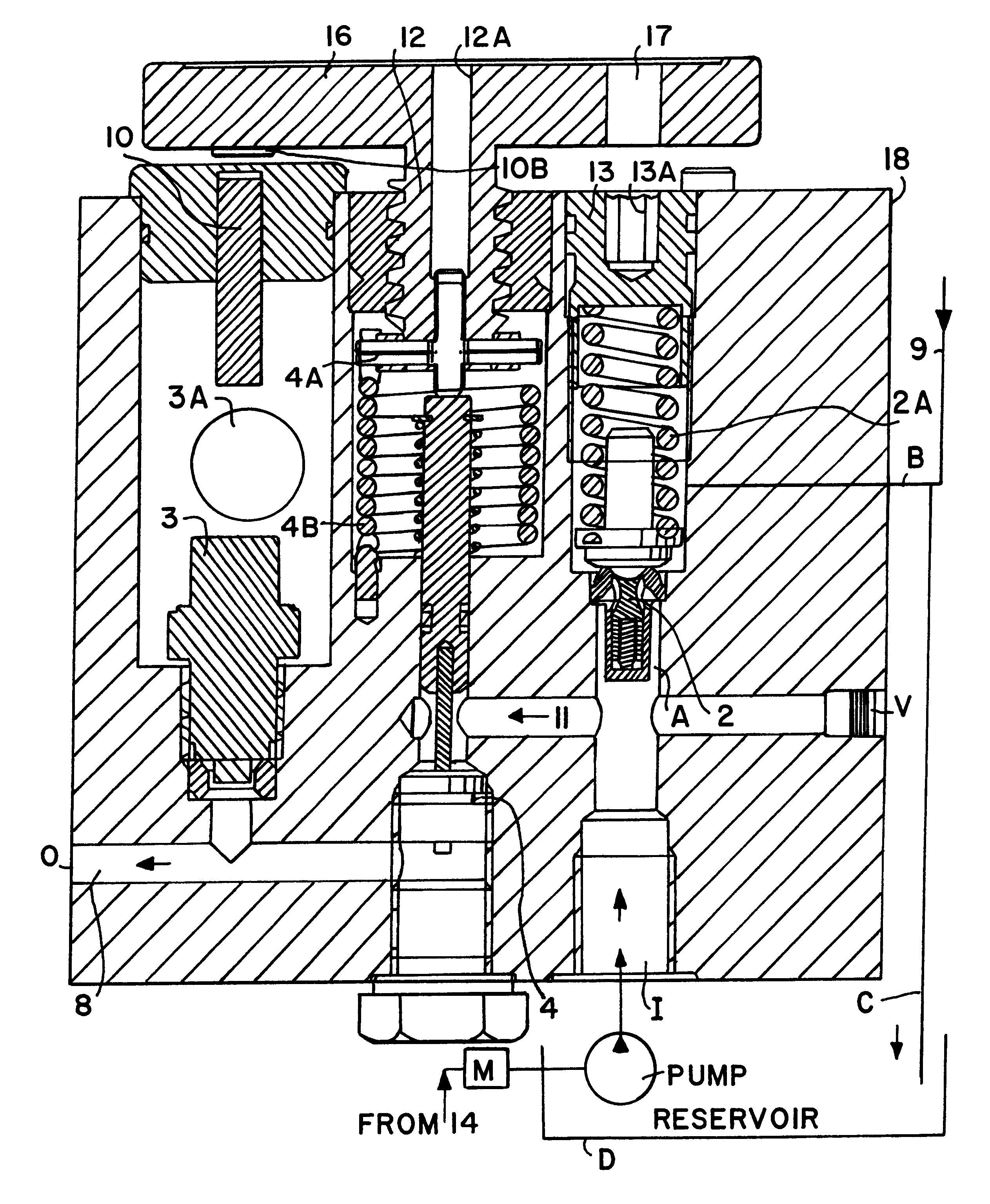
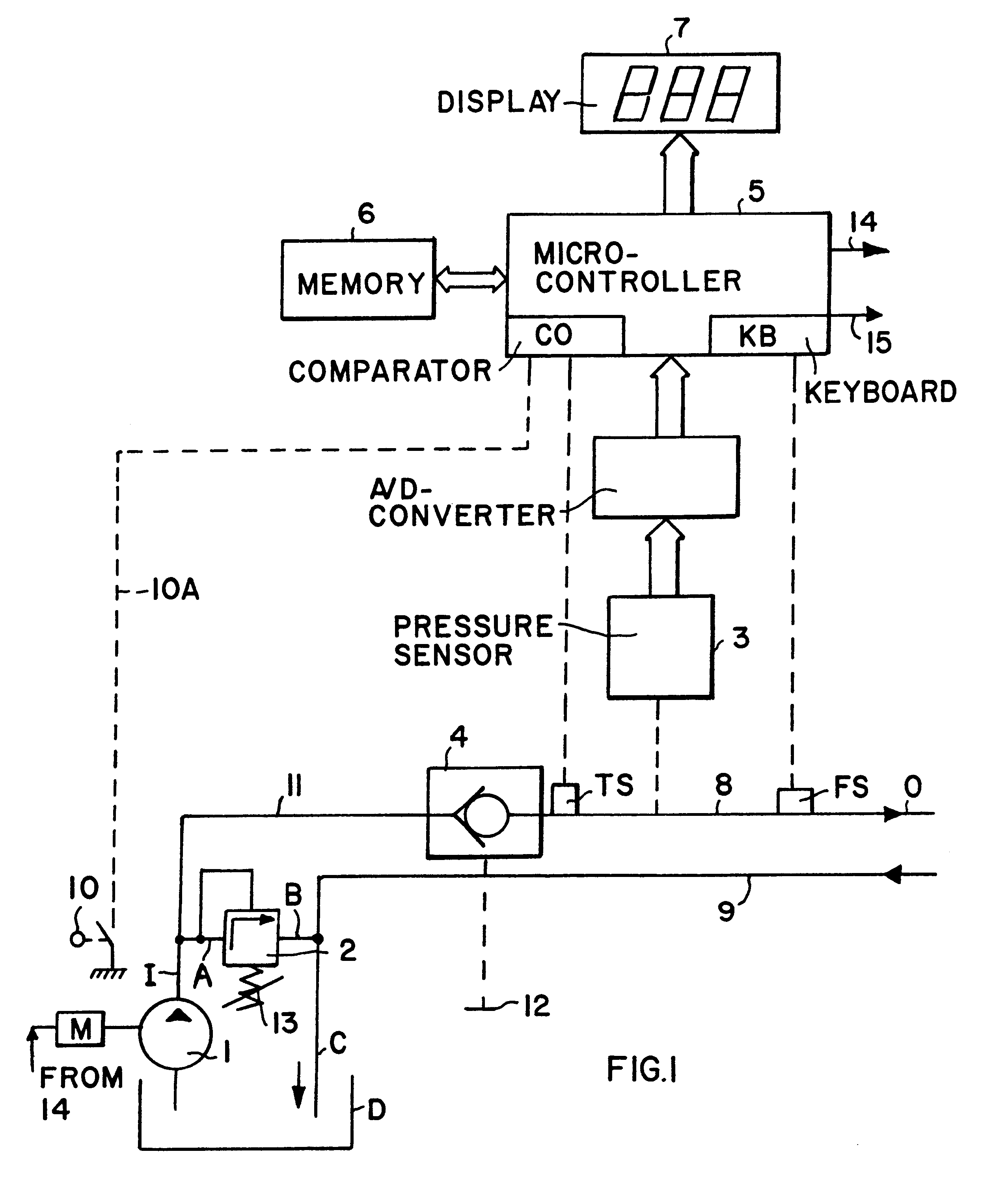
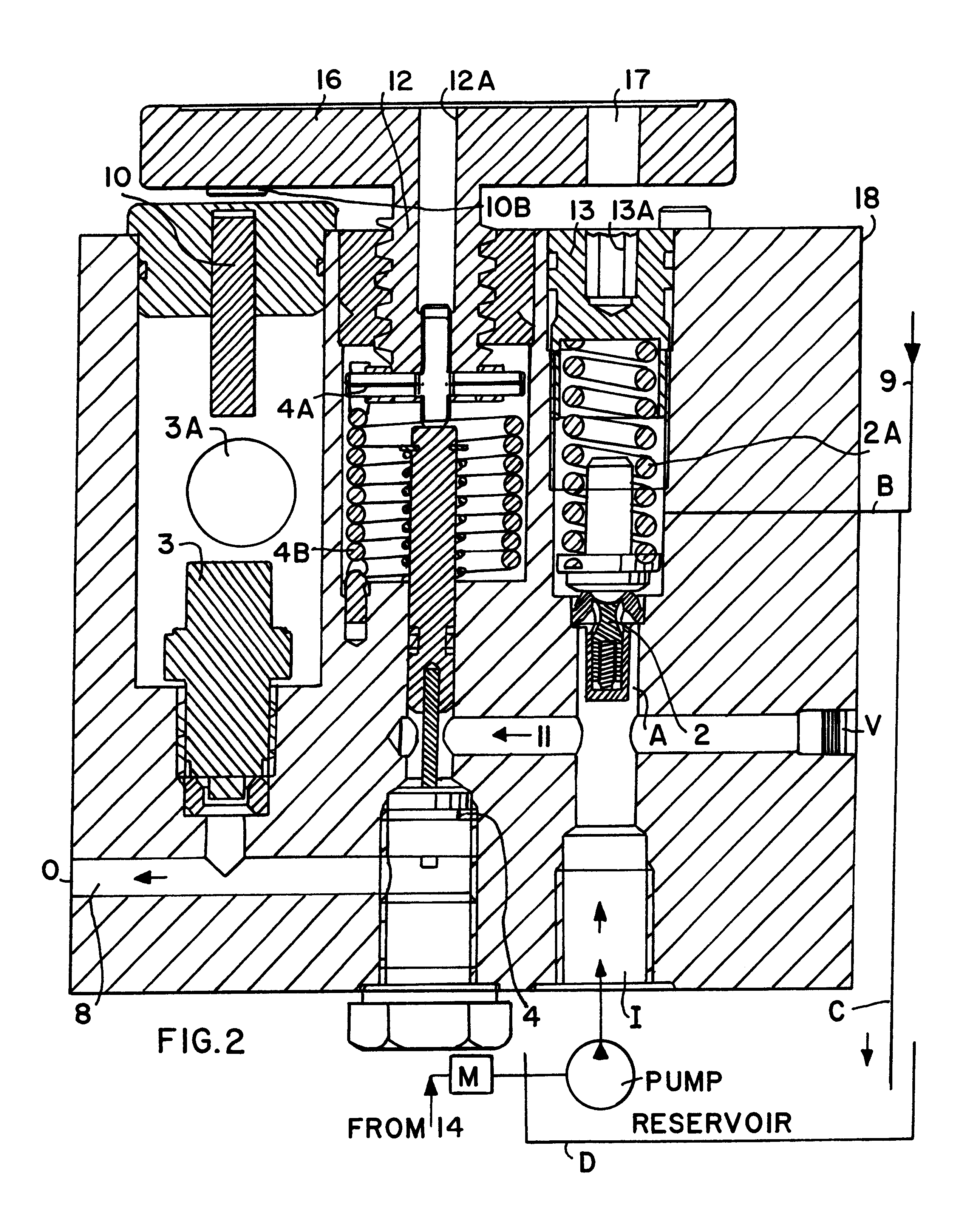
FIG. 1 is a block diagram that shows a pump 1 for generating the desired pressure in a pressure supply line or duct, which includes a pressure input I formed by a line 11 and a pressure output O formed by a line 8. The pressure output line 8 leads to pressure consumer elements, i.e. pressure-operated clamps or other devices that function dependent upon an adequate pressure supply. The pressure fluid returns to a reservoir D of the pump 1 through a return flow line 9. A pressure relief valve 2 controls the system pressure by bleeding excess pressure fluid into an overflow or by-pass line A, B, C which returns excess fluid to the reservoir D. A check valve 4 that statically seals the pressure input I from the pressure output O is provided between the pressure input line 11 and the pressure output line 8. According to the invention check valve 4 must be open, preferably fully open, as a first condition of any adjustment of the pressure relief valve 2 to a required rated system pressure...


PUM


Abstract

The rated system pressure in a pressure control system is adjusted through a pressure relief valve (2). In addition to the pressure relief valve (2), the system includes a check valve (4), a pressure sensor (3), a position switch (10), a first pressure adjustment member (13) for the relief valve, a second pressure adjustment member (12) for the check valve (4), an actuator (16), and a microcontroller (15) with a memory (6) and a display (7). Faults caused by pressure adjustment interactions are prevented by permitting an adjustment of the pressure relief valve only if the check valve is fully open and a pump provides pressure. For this purpose the actuator (16) of the check valve in its normal position prevents an adjustment of the pressure relief valve. Opening the check valve by the actuator permits adjusting the pressure relief valve (2) and the switch (10) operated through the actuator sends a signal to the microcontroller to drive the pump. When the check valve is opened, the pressure is equalized throughout the system, so that adjusting the response pressure of the pressure relief valve automatically adjusts the system pressure to a desired rated pressure.

Description

The invention relates to an apparatus and a method for controlling a rated system pressure in a pressure supply system such as a hydraulic system by simultaneously adjusting a pressure relief valve on a pressure generating or input side and operating a switch on the pressure consumption or output side of the pressure supply system.BACKGROUND INFORMATIONPressure supply systems such as hydraulic or pneumatic systems are operated by a pressure pump at a rated system pressure. When such systems are used in clamping operations, for example to hold a workpiece in a machine tool, it is often necessary to adjust the system pressure to a given situation requiring a different rated system pressure which may be higher or lower than the initially adjusted rated system pressure. Changing the rated system pressure, however, introduces a relatively large source of error or fault, since at least two elements that influence each other must be adjusted.Such pressure supply systems, especially hydraul...

Claims


Application Information

Patent Timeline
Patent Type & Authority Patents(United States)
IPC IPC(8): F15B11/00F15B21/08F15B21/00F15B11/028G05D16/20
CPCF15B11/028F15B21/087G05D16/2066F15B2211/20515F15B2211/20538F15B2211/25F15B2211/50536F15B2211/5151F15B2211/55F15B2211/6309F15B2211/6653F15B2211/30515Y10T137/8326Y10T137/2622
Inventor KROELL, HARALDPITZ, WALTER
Owner A ROMHELD
Why Eureka
Try Eureka