Rotary charging plug structure of a charger

a charging plug and charging plug technology, applied in the direction of secondary cell servicing/maintenance, electrochemical generators, coupling device connections, etc., can solve the problems of increasing manufacturing costs, incontinence, and inconvenient use, and achieve the effect of eliminating failur

Inactive Publication Date: 2001-08-14
SON KON
View PDF5 Cites 54 Cited by
  • Summary
  • Abstract
  • Description
  • Claims
  • Application Information

AI Technical Summary

Benefits of technology

It is a primary object of this invention to provide a rotary charging plug structure of a charger, using a blade base by integrally riveting blades to a shaft and support pro

Problems solved by technology

1. Because the horizontal shaft is inserted after the coupling plates are integrally joined to the blades by riveting, a frontal or a lateral impact applied to the blades may cause disengagement of the semi-circular protrusion 141, the spring 160, or the keyways 212 thereby causing inconvenience in use.
2. Such a structure consists a great number of components, which increases manufacturing cost arisen from produc

Method used


Image

  • Rotary charging plug structure of a charger
  • Rotary charging plug structure of a charger
  • Rotary charging plug structure of a charger

Examples


Embodiment Construction

A preferred embodiment accompanied with the drawings is explained, in details, as follows so as to clearly disclose this invention.

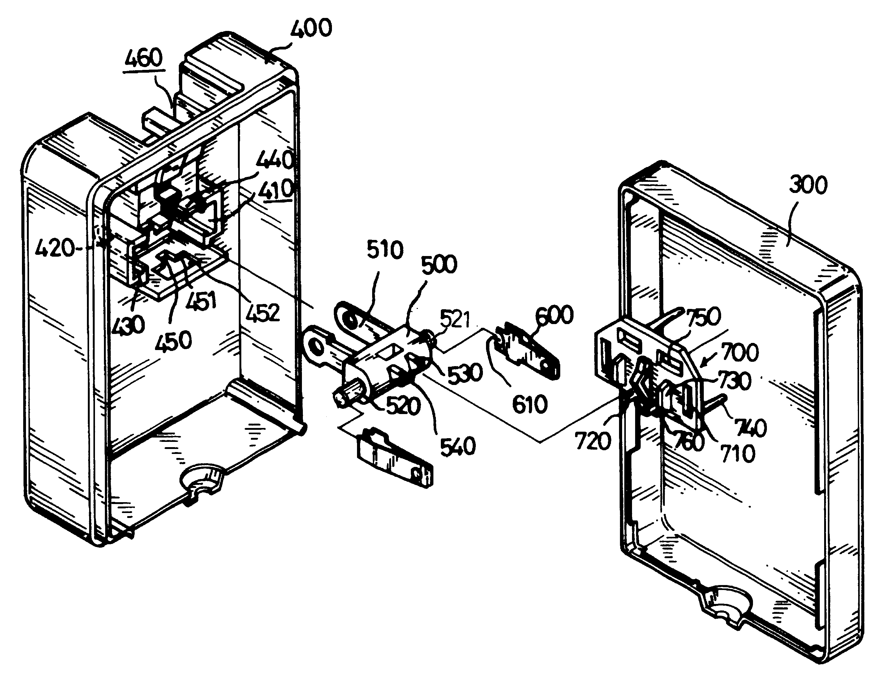
FIG. 3 is a perspective, assembled view of this invention; FIG. 4 is a perspective, exploded view of this invention. As shown in FIGS. 3 and 4, the structure of this invention comprises: an upper lid 300 to be matched with a lower lid 400 so as to receive a circuit board (not shown) therein, the lower lid 400 being provided with an outer receiving chamber 460 for receiving blades 510, and a receiving chamber 410 therein for receiving a blade base 500. The receiving chamber 410 is provided on each of opposing sides thereof with a U-shaped notch 420 for receiving a shaft 520. The U-shaped notch 420 and an inner wall of the receiving chamber 410 jointly form a groove 430 for receiving a conductive plate 600. The receiving chamber 400 is provided with clamping blocks 440 at an upper end and a {character pullout}-shaped through-hole 450 at a lower end thereof...


PUM


Abstract

This invention is related to a rotary charging plug structure of a charger, having: an upper lid to be matched with a lower lid so as to receive a circuit board therein, the lower lid being provided with a receiving chamber therein for receiving a blade base. The blade base is provided with two blades and shafts at each of opposing ends thereof. The shafts are each formed with an annular grove at a top end thereof for being integrally riveting to the shafts and includes the two stop blocks and a protruding block. The rear lid covers and urges against the blade base after placing the blade and the conductive plates into the receiving chamber. The rear lid includes a guide block at a center thereof to allow sliding movement of the protruding block of the blade base. Each of the through-holes and the guide block are provided with a push block therebetween for urging against the shafts. As such, the blades can be rotated within a 90° range. Further, the blades are prevented from disengagement upon experiencing a frontal or a lateral impact. This invention is also simple in its structure so as to reduce the manufacturing and assembly cost.

Description

This invention is related to a rotary charging plug structure of a charger, in particular to one that uses a blade base integrally formed by riveting blades to a shaft so as to prevent the blades from disengagement upon experiencing a frontal or a lateral impact.BACKGROUND OF INVENTIONA conventional rotary charging plug structure of a charger, such as that disclosed in ROC (Taiwan) Patent Application No. 82201253 entitled "Improved Rotary Charging Plug Structure of a Charger" (as shown in FIGS. 1 and 2), mainly comprises a housing 100 having walls, and a plug structure 200. The housing 100 includes a substantially L-shaped notch 110 that is formed with openings 120. The two openings 120 are formed therebetween with a receiving slot 130 for receiving an urging element 140. The receiving slot 130 is formed at a bottom thereof with a blind hole 150 at a location corresponding to where the urging element 140 is provided. The blind hole 150 may be provided with a spring 160 therein. The ...

Claims


Application Information

Patent Timeline
IPC IPC(8): H01M10/42H01R13/66H01M10/46H02J7/00
CPCH01M10/46H01R13/6675H02J7/0042Y02E60/10
Inventor CHEN, SHENG CHIA
Owner SON KON
Why Eureka
Try Eureka