
Method and apparatus for selectively connecting electrical circuits and components

a technology of electrical circuits and components, applied in the direction of electrical discharge lamps, coupling device connections, securing/insulating coupling contact members, etc., can solve the problems of large time, inability to be easily and dynamically modified, adding to the overall cost and complexity of modifying and creating new automobile designs, etc., to achieve the effect of efficient and relatively cost-effectiv

Inactive Publication Date: 2001-08-28
VISTEON GLOBAL TECH INC
View PDF31 Cites 61 Cited by
  • Summary
  • Abstract
  • Description
  • Claims
  • Application Information

AI Technical Summary

Benefits of technology

It is a third object of the invention to provide a relatively efficient and relatively cost effective method of manufacturing and / or creating electrical connection and power distribution assemblies, and certain terminal members contained within these assemblies.

Problems solved by technology

While prior junction boxes provided such a desired circuit, component, and electrical power distributive and connective interface, they suffered from several drawbacks.
Particularly, due to the complexity and the number of the various automobile circuits and components, prior junction boxes included and required the formation of a multi-dimensional, non-uniform, and relatively complicated stamped metal fret circuit pattern which required a relatively large amount of time to create, was "statically" designed to operate only with a unique circuit and component configuration, and was not capable of being easily and dynamically modified.
Typically, a new junction box design was required for each new model of automobile that was produced and for each model that was electrically modified from one year to the next, thereby adding to the overall cost and complexity of modifying and creating new automobile designs.

Method used


Image

  • Method and apparatus for selectively connecting electrical circuits and components
  • Method and apparatus for selectively connecting electrical circuits and components
  • Method and apparatus for selectively connecting electrical circuits and components

Examples


Embodiment Construction

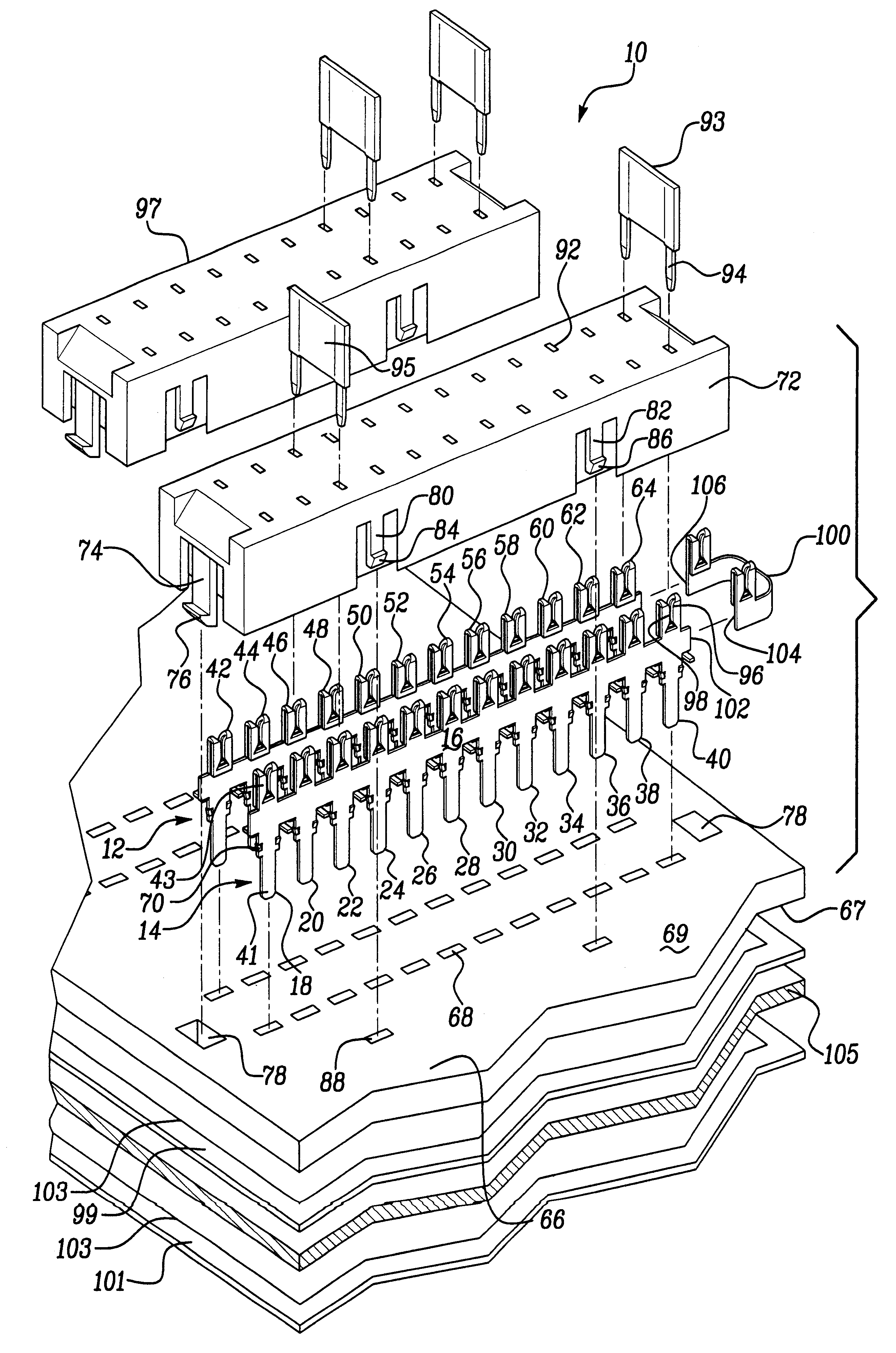
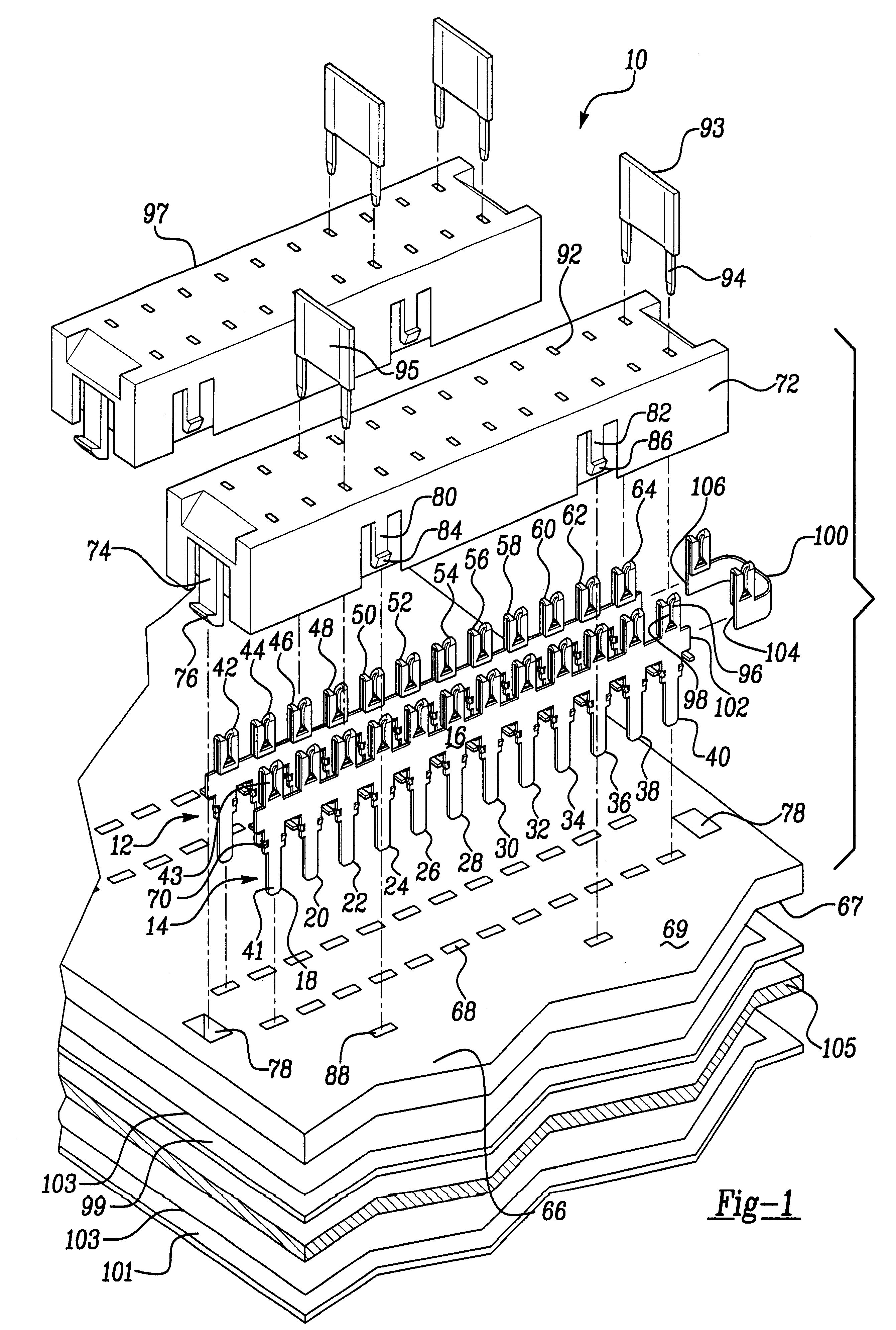
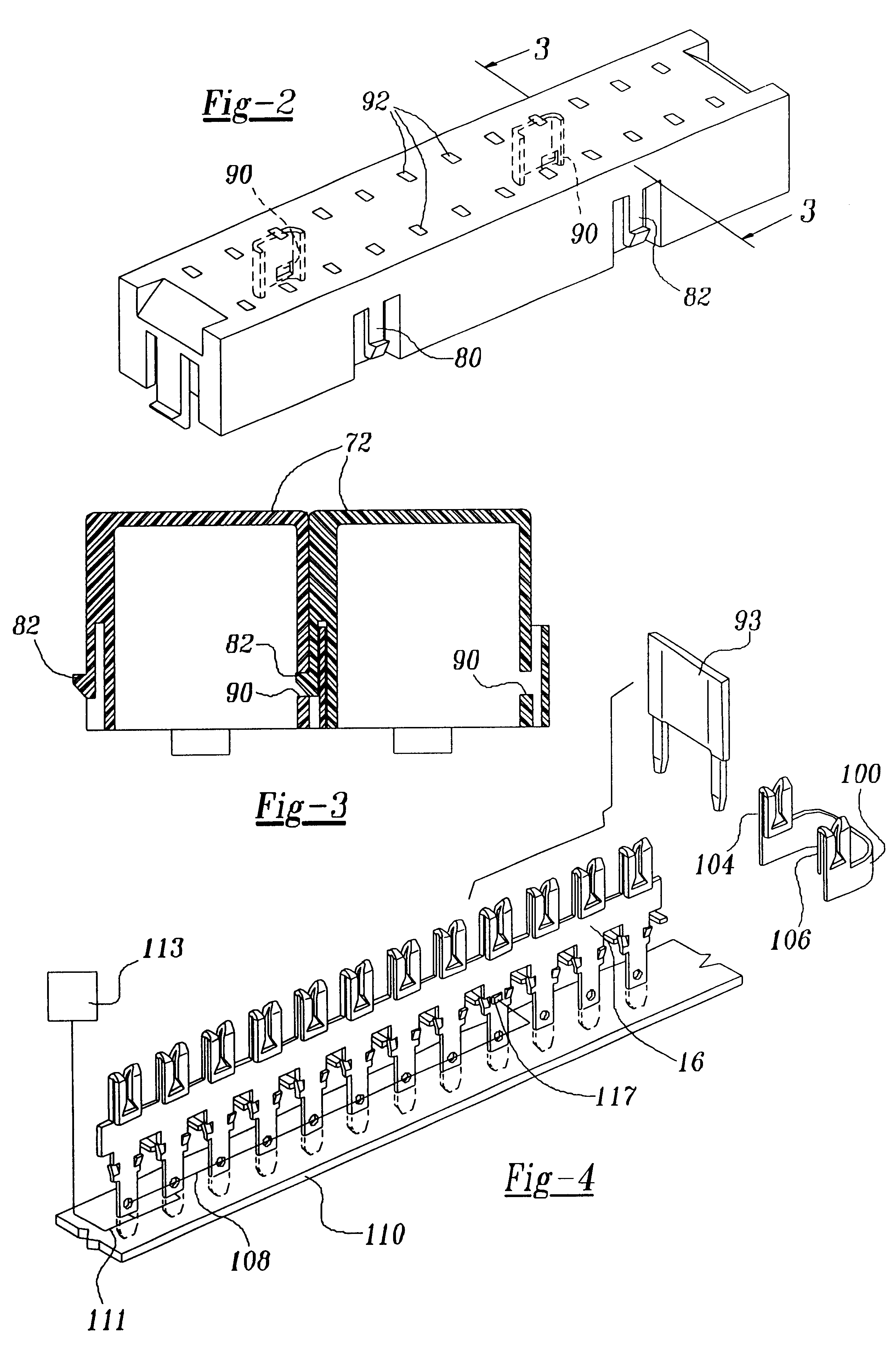
Referring now to FIGS. 1-4, there is shown an electrical connection and power distribution assembly 10 made in accordance with the teachings of the preferred embodiment of the invention. As shown, assembly 10 includes an array of substantially identical electrically conductive terminal members 12, 14, each having a relatively thin electrically conductive body or "lead frame" 16 including a plurality of integrally formed, evenly spaced, substantially identical, relatively thin, and electrically conductive blades 18-40, and electrically conductive receptacles 42-64. Blades 18-40 and receptacles 42-64 are integrally formed on opposed surfaces of the body 16, are mutually and linearly coextensive with the body 16, and respectively project from body 16 in opposite directions. Particularly, each receptacle 42-64 is paired with a unique one of the blades 18-40 and surfaces 41 and 43 are co-planar with body 16. In an alternate terminal embodiment, shown best in FIGS. 5 and 6, blades 18-40 a...


PUM


Abstract

An electrical connection and power distribution assembly 10 including a dynamically configurable array of substantially identical terminal members 12, 14 which are disposed upon a dielectric surface 66, which may be selectively connected to a plurality of automobile circuit assemblies 99, 101, and 110; which may selectively receive fuses 93 or other components; and which may be selectively interconnected and / or selectively severed to form a desired and / or required circuit and component interconnection scheme.

Description

FIELD OF THE INVENTIONThis invention relates to a method and to an apparatus for selectively connecting electrical circuits and components, and more particularly to a method and to an apparatus for fuseably protecting and for selectively distributing electrical power to these circuits and components.BACKGROUND OF THE INVENTIONElectrical circuit connection and power distribution assemblies, commonly referred to as "junction boxes," are used within automobiles to provide a convenient physical and electrical interface for the selective connection between the various automobile electrical circuits and between these circuits and various components, such as fuses and relays. Importantly, these automobile junction boxes also allow for the relatively efficient "troubleshooting" of these circuits by providing efficient access to the circuitry as well as providing an efficient and selective coupling and distribution of electrical power to these circuits and components. While prior junction bo...

Claims


Application Information

Patent Timeline
Patent Type & Authority Patents(United States)
IPC IPC(8): H01R9/24H01R29/00H01H85/20H01H85/00H01R12/16H01H85/147H01H85/153H01H85/22H01R33/95H02G3/16
CPCH01R9/2458H01R29/00H01H85/2035H01H85/205H01H2085/208Y10S439/949H01H2085/209
Inventor KRAUS, RICHARD ALLENBELANGER, JR., THOMAS DUDLEY
Owner VISTEON GLOBAL TECH INC
Learn More